
Author: scienceadmin

IMU And Robotics: What You Need To Know

In this article, we share a lot of information necessary for the purchase of your IMU according to your specifications.
You will find out how an IMU works and how to interpret its parameters.

At the end of the article, you will also find links to tests and resources.

Definition – What Is An IMU?

An inertial measurement unit (IMU) is an electronic component included in the family of sensors. It measures the acceleration of the sensor, the angular velocity and its orientation using a combination of accelerometers, gyroscopes, and magnetometers.

The Type I IMU is made up of accelerometers and gyroscopes, while the Type II IMU includes additional magnetometers.

Accelerometers, gyroscopes, and magnetometers measure data relating to a single axis (X: pitch, Y: roll, Z: yaw). In order to obtain information for the 3 axes, you must integrate three components of each (accelerometers, gyroscopes, and magnetometers) for a Type II IMU. A typical IMU sensor is 9 DoF (degree of freedom) including:

  • 3 accelerometers
  • 3 gyroscopes
  • 3 magnetometers

Some IMUs may have additional degrees of freedom with a temperature sensor, a GPS sensor, a pressure sensor, etc.
Based on acceleration, calculations of attitude, speed, and position can be performed.
Thanks to gyroscopes, the angular position can be calculated.

This data, provided by the IMU, is essential in mobile robotics. Indeed, they complement the LiDAR measurements and the odometric measurements.

Physics – How does an IMU work?

To understand how an IMU works, you must first analyze each subcomponent:

Sub-Component 1: The Accelerometer

An accelerometer is an electromechanical device used to measure acceleration forces. These forces can be:

  • Static, like the force of gravity
  • Dynamics like the forces of movement or vibration

Acceleration is the measure of the change in speed or speed divided by time. For example, a bicycle that accelerates from stopping at 30 km / h in five seconds has an acceleration of 6 km / h per second (30 divided by 5).

Sub-Component 2: The Gyroscope

A gyroscope is a device used to measure or maintain orientation and angular speed. It is a rotating wheel, or a disc, in which the axis of rotation is free to take any orientation by itself.

During rotation, the orientation of this axis is not affected by the inclination or rotation of the support, depending on the conservation of the angular momentum.

Sub-Component 3: Magnetometer

A magnetometer is a device that measures magnetism:

  • His direction
  • His strength
  • The relative change of a magnetic field at a given location

A compass is one such device that measures the direction of an ambient magnetic field. In this case, the Earth’s magnetic field.

ROS – IMU Data Transfer

All ROS-compatible IMU sensors publish their data on the topic/imu in the sensor_msgs / Imu.msg message format:

std_msgs / Header header

geometry_msgs / Quaternion orientation
float64 [9] orientation_covariance

geometry_msgs / Vector3 angular_velocity
float64 [9] angular_velocity_covariance

geometry_msgs / Vector3 linear_acceleration
float64 [9] linear_acceleration_covariance

Orientation

3D rotations and orientation can be represented using the form of Euler angles or in the form of a Quaternion.

Euler Angles

The Euler angles are composed of three angular values ​​for the X, Y and Z axes. Each rotation value is applied sequentially, that is to say successively.

Advantage

Euler angles have an intuitive format “readable to the naked eye”.

Limitation

In some configurations, the Euler angles suffer from a loss of freedom.

Indeed, during the successive application of the three rotations, it is possible that the first or the second rotation results in the third axis pointing in the same direction as one of the preceding axes so that the third value of rotation cannot be applied around a single axis.

Quaternions

Quaternions can be used to represent the orientation or rotation of an object.
Its representation consists of four numbers (referenced in the unit as x, y, z & w).

You should keep in mind that these quantities do not represent angles or axes and that you normally never need to access them directly.

Advantage

Quaternion rotations do not suffer from the loss of a DoF.

Limitation

A single quaternion cannot represent a rotation greater than 180 degrees in any direction and is not intuitively understandable.

Angular Velocity

The angular speed is represented by a three-dimensional vector (x, y, and z), the values ​​of the angular speed depending on the axes x, y, and z.

Linear Acceleration

The linear acceleration is represented by a three-dimensional vector (x, y, and z), the values ​​of linear acceleration depending on the axes x, y, and z.

Covariance

With regard to the sensors, the covariance is the coefficient of confidence relative to the accuracy of the sensor.

Covariance can be static based on sensor performance or continuously updated by changing over time based on the estimate of accuracy. It’s the same for IMU, they can have a static or dynamic covariance.

Each parameter has an associated covariance coefficient, hard-coded or processed by the sensor software, indicating how reliable the value can be.

Overview Of IMU Features

Energy Consumption

To determine the energy requirements of your robotic project, you must take into account the mode and duration of the operation of your machine.

These parameters are important if the sensor operates on battery:

  • Supply voltage in volts
  • Operating current in amperes
  • Wattage

Sensor Specifications

The digital resolution describes the overall detection capacity of your sensor and consists of two parts:

1. The distance => amount of movement that the sensors can take into account:

  • In the case of an accelerometer, this is measured in G forces.
  • Gyroscopes are classified according to the angular speed of rotation that they can quantify in degrees/second.
  • Magnetometers measure their capacities in µT, which can vary depending on the axis of the sensor (x, y, z).

2. Sensitivity => absolute number representing the smallest amount of change that can be measured and detected. For sensors, this is directly related to the number of bits reserved for the sensor in question. The more bits, the higher the sensitivity.

Zero gravity offset: the value of the accelerometer when no external force is applied, which is the minimum error detected.

Zero rate offset: the value of the gyroscope in the absence of angular movement, which may depend on the temperature.

Data rates: the number of measurements made during a given period of time. When choosing your IMU, make sure that the supported sensor rates match the needs of your applications.

Noise density: defined in units per square root bandwidth, typically:

  • ug/sqrt (Hz) for accelerometers
  • deg/s sqrt (Hz) for gyroscopes

Bandwidth: the range of frequencies in which an accelerometer or gyroscope operates.

Interfaces: what cable and communication protocol does the IMU and your embedded system use?

Temperature range: minimum and maximum ambient temperature sensors can operate safely to provide accurate measurements.

Output Parameters

Static precision: the precision of the sensor output when the device is relatively stable/stationary.

Dynamic precision: this is the precision of the sensor output when the device is in motion.

Rotation error: the difference between the output vector and the real vector, measured in degrees.

Heading Error: the difference between the output of the yaw axis and its actual value, measured in degrees.
Heading Drift: error accumulated over time.

RAW Accel / Gyro / Mag: the raw output of each sensor before any treatment.

Calibrated Accel / Gyro / Mag: output from each sensor after sensor fusion has been used to process and clean each signal.

Calibration

After examining the parameters of the sensor outputs, there is something else you need to consider: calibration. The calibration options you choose depend on your budget and the needs of your project.

Nominal: nominal calibration uses average values ​​for the sensor to give it an average performance.

Per-device: calibration by the device allows you to calibrate certain factors, such as the gain of the sensor, specific to each component. Depending on your application, you can choose to calibrate according to a single axis or several axes if your project.

Dynamic: If you find that the nominal calibration is acceptable, the output of your sensor can be further improved dynamically in the field. The characteristics of the sensor vary depending on the temperature and can be adjusted as the sensor is used in its final application.

Data Fusion Algorithms
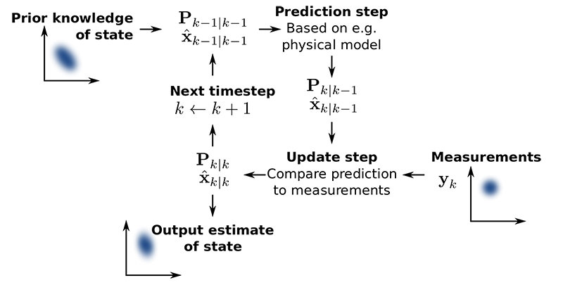
The Kalman Filter

The Kalman filter is a model implementation:

  • First, based on its model, the filter makes an assumption about the next sensor output value
  • He then takes the measured value and compares it with his assumption
  • Finally, he updates his model to make more precise assumptions for the next measurement.

Each sequence of data from the sensors is used to statistically improve the model in order to calculate the outputs. At the same time, the accuracy of the sensors is also judged.

The model depends on the sensor error and the application in question. For mobile robotic systems, real-world knowledge also tells us that physical objects move smoothly and continuously in space, rather than teleporting through space as samples of GPS coordinates might indicate.

This means that if a sensor that has consistently given excellent values ​​consistently starts to tell you unlikely things (like GPS / radio systems when you enter a tunnel), the credit rating of the sensors decreases in a few iterations of a few milliseconds until it begins to measure consistent values ​​again.

It’s better than just averaging because the Kalman filter can support most of its sensors which become temporarily inaccurate. At least one sensor is required which transmits relatively precise values. It ensures the proper functioning of the robot until the other sensors operate again.

The Kalman filter is an application of the more general concepts of Markov chains and Bayesian Inference, which are mathematical systems that iteratively refine their assumptions using evidence.

PID Filters

Simpler robotic systems can be fitted with PID filters. They can be considered as primitive Kalman filters supplied by a single sensor, all the iterative settings being cut and replaced by three fixed values ​​(KP, ki, and kd).

It is a correction system that adjusts the input through the control loop to obtain the correct output.

Even when PID values ​​are set automatically or manually, the whole process of “setting” (adjusting, stealing, judging, repeating) is an outsourced version of Kalman with a human doing the step of spreading beliefs.

Custom Filters

Real systems are often hybrid, somewhere in between.

ROS Packages For IMU

If you implement your robot software under ROS, it will be easier to buy sensors compatible with ROS. This means that the manufacturers have already developed a ROS package to make the sensor interact with ROS. This will save you time.

With regard to the IMU, the sensor will publish the raw or processed data, depending on the implementations of your IMU, on the topic/imu. Then on ROS, you can subscribe to the topic to get data to use it for navigation, for example.

Some ROS packages are already implemented and up to date:

  • imu_transformer: This package provides a node / nodelet combination which can be used to transform IMU data from one TF frame to another
  • imu_tools:
  1. Imu_filter_madgwic: Filter that merges the angular velocities, accelerations and (optionally) magnetic readings of a generic IMU device in an orientation based on the algorithm of Sebastian Madgwick
  2. Imu_complementary_filter: Filter that merges the angular velocities, accelerations and (optionally) magnetic readings of a generic IMU device in a quaternion to represent the orientation of the device on the global frame, based on the algorithm of Roberto G. Valenti
  3. rviz_imu_plugin: a plugin for rviz that displays sensor_msgs:: Imu messages
  • imu_utils: Package that tracks IMU performance on Matlab

How To Choose Your IMU?

Make your choice according to the requirements of your project. The cheapest IMU provides only raw values, while the UM7 filters the processed values ​​and publishes them directly in a ROS message.

The performance is quite similar even for the most expensive IMUs. The difference is in the additional services and implementations:

  • Integrated calculations
  • Integrated filters (very efficient: IMU SBG Systems )
  • Integrated microcontroller
  • Map library (Arduino, Raspberry pi, etc.)
  • ROS compatibility
  • Interface
  • Integration with GPS data ( Ellipse 2 Micro INS inertial unit from SBG Systems )

What Is The Performance of the IMU?

An IMU sensor is a useful component to add to your robot. It will give you information on attitude, orientation, position, speed, acceleration, rotational speed if the values ​​are calculated.

However, you should keep in mind that the IMU is subject to drift errors. Indeed, errors accumulate over time since the new values ​​are based on the previous ones.

In addition, the IMU, using the magnetic field to calculate values, can be altered by other magnetic fields (motor, metallic structure, etc.) which can give huge errors.

You can implement fixes and filters to reduce this error, but the IMU error will continually drift and increase.

One way to solve this problem is to take into account the value of covariance (confidence coefficient), which can change over time if it is dynamic.

Another way is to add a GPS sensor. Indeed, the GPS signal can update the value of the IMU and correct its drift error.

Looking for real results, you will find online a test of online visualization of the data of an IMU and of an EMG sensor connected to a wrist, which will give you an overview of the error of the IMU (parts 2.1 and 3.1).

This other article lists and describes all the biases of the IMU leading to errors.

Conclusion: Advantages And Disadvantages Of IMU

Benefits Of An IMU

  • The inertial navigation system is independent of all external information and does not consume too much energy
  • The inertial navigation system can provide the location, speed, altitude, angle data, and resulting navigation information is continuous
  • High-frequency measurement and good stability

Limits Of IMU

  • Using information from the integrated navigation system, positioning error increases over time and long-term accuracy is low
  • Long initial alignment time required before each use
  • Time information cannot be given

Robots Will Never Replace Teachers But Can Boost Children’s Education

Robots can play an important role in educating young people, but will never completely replace teachers, suggests a new study.

In Science Robotics, scientists explain that social robots are proving effective in teaching certain subjects as restricted as vocabulary or prime numbers.

But the current technical limitations – particularly with regard to speech recognition and the capacity for social interaction – mean that their role will be essentially limited to that of assistants or tutors, at least in the near future.

The study was led by Professor of Robotics Tony Belpaeme, from the University of Plymouth and the University of Ghent, who has worked in the field of social robotics for about two decades.

He said: In recent years, scientists have started building robots for the classroom – not the robot kits used to learn technology and math, but social robots capable of teaching.

The pressures on teaching budgets and the need for more personalized teaching have led to the search for technological solutions.

In the broadest sense, social robots have the potential to be part of the educational infrastructure, just like paper, whiteboards, and tablets.

Robots can free up valuable time for teachers, allowing them to focus on what people still do best: providing a comprehensive, empathetic and rewarding educational experience.

The current study, done in collaboration with academics from Yale University and Tsukuba University, has reviewed more than 100 published articles that have shown that robots are effective in increasing results, mainly due to their physical presence.

However, Professor Tony Belpaeme also explored in detail some of the technical constraints, pointing out that speech recognition, for example, is still not robust enough to allow the robot to understand utterances uttered by young children.

He added that the inclusion of social robots in school curricula would pose significant logistical problems and could actually entail risks, as some children are considered to be too dependent on the help offered by the robots rather than simply using them when they are in trouble.

In their conclusion, the authors add: Besides the practical considerations of introducing robots into education, there are also ethical issues. How far do we want our children’s education to be delegated to machines?

Overall, learners are satisfied with their experiences, but parents and teachers are more cautious.

Despite this, robots hold great promise for teaching small subjects whose results almost match those of human tutoring.

So, although the use of robots in educational environments is limited by technical and logistical challenges at the moment, it is very likely that the classrooms of the future will include robots that will assist a human teacher.

5 Errors Of Beginners In Welding

Are You Making These Mistakes?

Don’t worry, I made all of these mistakes myself. And sometimes it still works. But by correctly learning the welding technique, you reduce the chances of operating errors in your circuit, due to bad welding.

Note: in French, there is confusion and amalgamation between welding and brazing. In electronic wiring, it will always be the soldering process even if the term soldering is used.

1: Removing The Iron Before Applying The Solder

When I teach someone how to weld, I usually say that you have to heat the spindle and the pad first and then apply the solder.

But sometimes my explanation is not clear enough. I have seen students heat the pad and pin, then remove the soldering iron before trying to apply the solder.

Unfortunately, this cannot work well. When you remove the iron, the pad and the pin cool down quickly; the solder cannot melt.

2: Heat Only The Tablet

Another common mistake is to only heat the pellet. The person heats the patch, then applies the solder. But since the component spindle has not been heated, the welding does not take place with the spindle.

You will have the same connection fault if you only heat the component’s tab. You will get a drop of solder which will “float” above the patch.

3: Cut The Component Leg Too Short

To have a circuit that looks clean and pleasant to look at, I have seen students push the components as far as possible into the holes, then cut the tab so that it does not protrude from the board.

This makes it difficult to weld the spindle. The cabler then ends up with a solder covering the hole but, which is not actually connected to the pin.

4: Use Of Too Little Solder

Some beginners are afraid to use too much solder, so they deposit too little. The amount of solder is not necessarily the most important point, but it is generally preferable to apply a good dose of solder from the start.

You will thus obtain complete soldering which will ensure a correct connection of the assembly.

5: Fear Of Overheating The Assembly

The circuit can support more than it seems. I have seen students worried about overheating the circuit. They, therefore, try to solder the assembly in less than a second to keep the card out of possible overheating. Today we use lead-free solder (tin, silver, copper) and the melting temperature is 217 degrees Celcius.

It is certain that you can damage the components if you heat them too long, but that’s not the thing to worry about at first.

It is, therefore, necessary to heat the component chip assembly correctly (with a fault at 350 ° C).

Robots In Education

Does it make sense to have a robot as a teacher?
Is the presence of a robot used as an educator beneficial?
Well, it depends if you are an adult or a child. The following article reveals some results of a study on the influence of a robot educator.

Young children have been shown to be much more likely than adults to have their opinions and decisions influenced by robots.

A study from the University of Plymouth in England compared the way adults and children perform an identical task in the presence of peers (therefore humans) and humanoid robots.

The results showed that, although adults are often influenced by their peers, they can resist the persuasion of robots.
However, children aged seven to nine were more likely to give the same answer as the robot, even if they were clearly incorrect.

The study used the Asch paradigm, which asks people to look at a screen with four lines and indicate which lines are the same length.

When alone, people almost never make a mistake, but when they experience others, they tend to follow what others say.

Single children had an average score of 87% at the end of the test. This percentage dropped to 75% when they were joined by robots. And among the wrong answers, 74% corresponded to those of the robot.

By posting in Science Robotics, the scientists say the study provides an interesting insight into how robots could be used positively in society. However, they also say that this raises some concerns about the potential for the negative influence of robots on vulnerable young children.

The research was directed by researcher Anna Vollmer and Tony Belpaeme professor of robotics from the University of Plymouth and the University of Ghent.

Tony Belpaeme Says:

This gives an interesting overview of how robots could be used positively in society. People often follow the opinions of others and it has long been understood that it is difficult to resist the appropriation of the views and opinions of the people around us. This is established as a rule.

As we now find robots at home and in the workplace, it is interesting to see that children also comply with them.

Our results show that adults do not comply with what robots say. But when we did experience with children, they did.

This shows that children can perhaps have more affinities with robots than adults, which begs the question: what if the robots suggested, for example, which products to buy or what to think?

Robots are already used in education (like the Zora robot) and can be beneficial in learning STEM. In these environments, the robot is in a position where the information it provides can significantly affect the children with whom it interacts.

Some protective measures must be put in place, but used in the right way, these robotic educators could considerably improve the education of children.

But will robots replace teachers or will their roles be limited to that of assistants or tutors?

Why Robots Should Be Used In Schools

As robots slowly infiltrate our daily lives, there should certainly be more in schools. This would help children get used to automation and gain experience in the areas of technology and science that dominate the labor market.

So why should schools start using robots in their lessons?

There Is Everything You Need To Get Started

Robotics is a subject that can be taught at any level or ability. The range of educational robots on the market, like LEGO® Education products, for example, covers all the key stages.

There are construction robot kits and programming examples suitable for four-year-olds.
Many products offer lesson plans and coding examples; they can be modified to suit all class levels.

From Scratch To C Arduino

Getting started with the Scratch programming language is ideal for young children. Coding is done simply with icons which is enough to align on a line to carry out a programmed sequence.

In a more advanced level of Scratch, it is possible to program your robot with blocks. With this special robotic version, the learner (8 years and over) can program conditions, functions, and variables. In this context, we are getting closer to the real syntax of programming.

Later, the Arduino C language will naturally impose itself from the age of 14.

Use Robotic Kits

You can use the robotic kits to teach other knowledge and skills. Above all, the idea of ​​introducing robots into schools is to learn what robots are.

Building and coding robot kits put children in a position where they manually manipulate sensors and motors, which helps improve motor skills and coordination.

In addition, you can also use robotics to introduce a reflection on real situations from the world around us. Children can learn about climate change, architecture, and engineering, as well as other topics such as biology by building and designing humanoids or animals, motorized platforms, bridges, and other structures.

Getting students to build robots introduces practical skills, where they can work as a team and exercise their communication, collaboration and critical thinking skills.

It is important to note that the introduction of robots in the class prepares children for the workforce of the 21st century. The workplace is changing rapidly and more and more industries are turning to automation (factories, sales areas, logistics, etc.). This forces students to study science, technology, engineering and mathematics ( STEM ). It has been reported that 50% of today’s children will have a job that does not yet exist. So they have to prepare!

The introduction of robotic kits provides a basis for teaching computer programming. By starting with a physical robot and learning by demonstration, learners will find that the theoretical aspect is easier to grasp.

Taking robotics courses promotes innovation and students develop entrepreneurial skills since construction and programming require creative thinking.
By giving students the opportunity to explore robotics and engineering, they can create their own programs and allow them to watch the program sequences unfold in real-time.

Finally, playing with robots is fun and you will always learn and remember information better when it is fun.

Study While Having Fun

STIM is a program based on the idea of ​​educating learners in four specific disciplines – science, technology, engineering, and mathematics – in an interdisciplinary and applied approach. Rather than teaching the four disciplines as separate subjects, STIM integrates them into a coherent learning paradigm based on real-world applications.

Two Popular Credit Cards

One million Arduino cards and clones have been sold every year since 2013 and more than 65 million blue CB cards are in circulation.
All blue cards.
Which do you use most often?

Credit Card CB

The CB blue card is a French invention born in 1967 to develop the use of the bank card to pay in any store.

In 1964 Roland Moreno invented the memory card or smart card.

It was in 1986 that we saw the appearance of the first bank chip card resulting from the combination of the two inventions.

Arduino Board

In 2002, Massimo Banzi started teaching computer science for physical systems. He teaches his students how to use and program an electronic card to create “prototypes of interactive objects”. The electronic cards used and available at the time were difficult to use in the context of learning (cards for industrial use, Windows, size, cost, etc.).

Massimo, therefore, imagines a complete and tailor-made solution called Programma: a development environment, a simple programming language, an electronic card that you can make and wire yourself and tutorials.

We can well imagine the enthusiasm and satisfaction of the students to work with this unified, simplified and efficient environment.

But Massimo wants to go further in his approach. He wants to transform the success of Programma into something universal and accessible to a large audience.

Massimo BANZI 

In 2005, with four other designers or computer scientists like him, he created Arduino. It is a printed circuit equipped with a small microcontroller, a serial link and especially small holes allowing the connection of sensors (temperature, humidity, light, sound, vibration, push-button) and actuators ( LED diodes, motors, displays…).
The core of the Arduino project development team is made up of Massimo Banzi (Italy), David Cuartuelles (Spain), Tom Igoe (United States), Gianluca Martino (Italy), David Mellis (United States) and Nicholas Zambetti (Italy).

From left to right: David Mellis, David Cuartuelles, GIanluca Martino, Massimo Banzi,

Arduino is “Open Source”. This means that you can download the original diagram and use it to make your own map and sell it without paying copyright. “Open Source” has made it possible to rapidly diffuse the Arduino concept around the world to generate a very large community that is constantly improving the cards.

In 2017, there were approximately three million units sold, not counting counterfeits or legal copies.
The number of users greatly exceeds this because anyone can make their Arduino board. The only Chinese copies distributed are estimated at three or four million copies.

The Polyphonic Music Revolution

Until about 1930, only mechanical processes could be used to produce sounds (percussion, string or wind instruments). The invention of the triode in 1906 (vacuum tube with three electrodes) allowed the development of all kinds of electronic devices. We knew how to artificially create music by using alternating currents, that is to say, electronic oscillations, generated either mechanically (alternators with musical frequency), or also by tube oscillators, or even by cells photoelectric acting on a loudspeaker “motor”.

Small Historical Summary

In 1927 Pierre TOULON and Krugg BASS invented the Cellulophone, an electric musical instrument that uses a photoelectric sound generator with an optical disc (celluloid disc pierced with slots).

In 1928 the patent for the first model “Ondes-Martenot” was registered (lamp oscillator).

In 1929, with 700 tube oscillators, for 70 notes and 10 timbres, two French engineers Armand GIVELET and Edouard Eloi COUPLEUX developed an electronic organ using more than 1000 tubes. It is the first fully polyphonic instrument.

In 1938 Jerome MARKOWITZ files the first patent (US Patent) for the stable oscillator.

The Schmitt trigger invented by Otto H. SCHMITT was then the most widespread generator because it was quite easy to make.

Diagram of the thermion trigger of Otto H. SCHMITT

The simple two-triode circuit that is described provides positive stop control with any desired differential from 0.1 volts to 20 volts. Less than 10 -6  A is required at the input, but up to 20 mA at 200 V is available at the output. The output can be taken on either triode; one is on while the other is off. Positive or negative control is possible. The operating cycle takes approximately 10 µs.

New Synthetic Organs

From 1935 two very sophisticated instruments enriched the range of organs intended to replace the bulky and expensive sound titans, which boast the galleries of cathedrals. These two remarkable newcomers are the Welte photoelectric organ made in Germany and the Hammond electromagnetic organ built in the United States.

The Hammond electromagnetic organ, in particular, is able to perform at the discretion of the performer a practically unlimited number of combinations of timbres, thus allowing the musician to really “create” the sounds suggested by his musical inspiration and not only combine the few fixed timbres of the classical orchestra.
It was, for the time, a whole revolution in the field of polyphonic music that already announced the constant progress of sound synthesis by purely electric processes, thus achieving a “symbiosis” of science and art.

“WELTE” Organ

The Welte-Lichtton-Orgel, designed by Edwin WELTE in Germany between 1932 and 1935, was one of the ancestors of the electronic organ, operating using optoelectronic sound generators.

The operating principle consists of spinning, at a constant speed, glass discs printed in the manner of the optical soundtracks of the first talking cinema.

These glass trays are printed with 18 different waveforms giving three different timbres for all the octaves of each note.

A sensor consisting of a photoelectric cell is placed in front of each track and captures the variations in light from a light source located on the other side of the disc. The variations are then amplified and reproduced on a loudspeaker.

“HAMMOND” Organ

The Hammond organ works by electromagnetism.

The generators making up this organ are also extremely simple. They are toothed wheels rotating in front of sensors made up of coils with soft iron cores equipped with a magnet. An axis driven by a synchronous motor carries cogwheels from 2 to 192 teeth.

When passing in front of the sensor, the teeth of a wheel cause the latter to change its magnetic state. This modification induces an alternating current in the coil, the frequency of which is determined by the number of teeth passing per second in front of the end of the magnetic core.

Retrospective

Pure Synthetic Music

It is remarkable that each progress in instrumental technique was followed almost immediately by a broadening of the musical inspiration of the composers. Thanks to sound synthesis, it becomes possible for inspiration to manifest itself at the cost of certain learning.

In fact, since we know how to record all known stamps on film, then reproduce them thanks to the photoelectric cell, nothing stands in the way of photographic recording, we replace in the sound player a strip created from scratch and the only thanks to our inspiration. This is what the German physicist Pfaenninger did, by drawing curves on a strip and then scrolling through this strip in an appropriate reader.

A second synthesis process was studied, in particular by the Italians Gennelli and Pastori. It is an electrical reconstruction of the human voice always by the process of dosing harmonics.
In this process, the generator is no longer followed by more than five filters corresponding to the fundamental emitted and to four higher harmonics. The generator is of the tube type, which makes it possible to vary the fundamental frequency.
This process only authorizes the creation of vowels, which can be produced with absolute purity.

Octave Transposition

When it comes to reproduced music, film or disc, it is possible, starting from the music performed by classical instruments, to create new timbres, more perfect than real timbres, also more pleasant, by the process of artificial transposition.

It was a Russian, Mr. Yankowski, who first had the idea of ​​this transposition.
He had noticed that, in certain instruments, the timbre, particularly rich in a certain range, became nondescript, even unpleasant in others.

It is undeniable, for example, that the treble of the piano is infinitely drier than the medium or the bass.
On the other hand, the lightness of the violin on the chanterelle does not persist on the other strings.

By means of the recording, it becomes possible to transpose from one octave to the other a passage executed in the most pleasant range of an instrument. Suppose we wanted to get the 5 of the piano, already high, less pleasant than the 3 of 435 periods: we record the passage taking the octave of the 3 as a base, but, on reproduction, we will play the recording to the player four times faster than it was recorded. If on the recording, the movement has been slowed down four times, it will be found normal during reproduction, but the notes, rich in timbre, of the 3 will become the 5 sought.

In this way, there is much to seek and realize, because the artistic possibilities thus offered, to inspiration are considerable by combining the processes of sound synthesis.

Keyboard

During its evolution, the keyboard of an organ progressively went from 2 to 5 octaves. Today we consider the 5-octave 61-key keyboard (do 1 to do 6 ) as the generally adopted standard.

How To Become A Robotics Engineer

Building robots is one thing, but it takes skilled people to design them. The role of the robotics engineer is to direct the design and construction of prototypes before mass production can take place.

Robots can be installed everywhere: in factories, hospitals, cars, trains, power plants, homes, gardens, etc. It also requires engineers specialized in maintenance and bringing together skills of assembler, mechanic, electrical engineer and automation engineer (electronics + programming).

You are passionate about robotics and perhaps you have already followed an initiation by consulting websites and by using Arduino boards and robotic kits for example…
Good!

You now want to go further, make it your job, rub shoulders with robots every day …
Why not?

Here is a 12-step guide filled with tips and links to free courses to start your career as a robotics engineer.

Learn The Theoretical Basics

1. Practice Basic Coding To Be Able To Program Your Robots

Coding is a fundamental part of robotics and you must know how to use variables, implement conditional statements, use functions and write new ones. Choose a programming language and study it yourself or take coding lessons to improve your knowledge.

The Arduino development environment allows you to get started easily to familiarize yourself with the instructions in C.
See at https://www.arduino.cc/en/Main/Software.

The most popular coding languages ​​for robotics are Python, C and C ++.

Coding Resources

  • Begin and learn coding: https://mooc-francophone.com/cours/apprendre-a-coder-pour-les-vrais-debutants/
  • Learn to program in C: https://openclassrooms.com/fr/courses/19980-apprenez-a-programmer-en-c
  • Program in C ++ language: https://openclassrooms.com/fr/courses/1894236-programmez-avec-le-langage-c
  • C ++ course by Patrick Trau: http://ptrau.free.fr/program/cpp/
    Lessons and tutorials to learn C ++: https://cpp.developpez.com/cours/
  • Learn the Python programming language: https://python.doctor/
  • Lessons and tutorials to learn Python: https://python.developpez.com/cours/
  • Python: https://www.coursera.org/specializations/python

2. Learn Linear Algebra

Basic algebra is essential both to program a robot and to refine its code. Take algebra lessons in high school and college, or study algebra yourself to strengthen your math skills.

If you have problems with math and are still a student, ask your math teacher for help. Many schools also have math help labs to teach key concepts to exceptional students.

Math clubs also exist to “reconcile students with math” (bridge workshops, chess, cryptography, games, graphs…).

Math Resources

  • Online course: https://fr.khanacademy.org/math/linear-algebra,
  • http://www.mathematiques.club/,
  • http://culturemath.ens.fr/category/generalites-270,
  • http://www.maths-buc.fr/,
  • http://www.parimaths.fr/,
  • http://www2.animath.fr/spip.php?article2706,
  • https://mmi-lyon.fr/?site_club=club-de-mathematiques-discretes,
  • Finished sequences and differences (pdf).

3. Study Physics

Building robots involves understanding how your robot moves and interacts with the outside world. If you haven’t taken a physics course yet, sign up for an online program or learn the basics of physics on your own.

Many web-based institutions, such as KhanAcademy and The Open University, offer courses in physics, math and even computer science for free.

Physics Resources

  • Online course: https://fr.khanacademy.org/science/physics.

4. Study IT

Robotics is closely linked to computer science and a good understanding of the latter is essential for learning the former. Study computer science to acquire basic skills and try to keep up to date with articles or websites on computer science.

Many community colleges offer online or in-person computer classes at a reduced cost, even if you don’t sign up for a program.

Computer Resources

  • Data and algorithmics: http://ptrau.free.fr/program/algo.htm,
  • Infographic: http://ptrau.free.fr/program/infogr.htm,
  • Online course: https://www.khanacademy.org/computing/computer-science,
  • https://www.college-de-france.fr/site/audio-video/index.htm and do a search with the keyword IT and check the course section,
  • Example of a computer course by Gérard BERRY at the Collège de France: https://www.college-de-
  • france.fr/site/gerard-berry/course-2018-12-13-16h00.htm ,
  • Search the web with Ecosia: https://www.ecosia.org/search?q=apprendre+le+codage+informatique.

Websites Offering All Disciplines

  • http://www.open.ac.uk/,
  • https://www.coursera.org/,
  • https://fr.khanacademy.org,
  • https://www.college-de-france.fr/,
  • https://openclassrooms.com/fr/courses.

Develop Your Robotics Skills

5. Build Your First Robot Using A Kit Or By Designing It Yourself

You can buy robots online or at many electronics stores. Start with simple robots. As your experience progresses, move on to more complex patterns over time.

Once you have acquired basic robotics skills, purchase a construction kit and build your robot using coding, math and manual DIY based on the instructions in the kit. You can also create your prototypes using parts and tools available in most hardware stores or purchased in DIY or model stores.

6. Take Robotics Lessons

While studying robotics yourself is useful, robotics lessons can teach you advanced techniques. Ask your local colleges or associations if they offer robotics lessons or sign up for an online course to develop new robotics skills.

Robotics Course Resources

  • https://openclassrooms.com/fr/courses/4262331-demarrez-votre-projet-avec-python
  • https://www.khanacademy.org/science/electrical-engineering/robots
  • https://www.khanacademy.org/science/electrical-engineering/lego-robotics

If you don’t have time for a robotics class, try reading books or articles on robotics and books on drones instead.

7. Join A Robotics Club

To share your passion with others and receive advice, joining a club, a fablab or an association is a good solution. Robotics is not just a hobby. If you want to build robots with other people, this can also be a way to build lasting friendships. Join the robotics club of your school or your municipality or the neighboring city to share your hobby with other people and learn new ways to build robots.

If you can’t find a robotics club in your area, consider setting up your own.

8. Take Part In Robotics Contests

When you are ready to present your projects and you have learned to program basic robots, enter your inventions in a local contest or in a big robotics contest. No matter how you do it, robotics competitions can be a great way to test your robots and learn how to improve them.

If you are not comfortable entering a competition, you can always attend first. You can not only get an idea of ​​what robotics competitions look like, but you can also find inspiration for your own robots by looking at all forms of competitions.

Study Advanced Robotics

9. Learn Trigonometry And Statistics

While linear algebra is enough for basic robots, you may need to learn advanced math to build complexes. Study trigonometry or statistics yourself, or take a course online or at a local college.

If you have trouble with advanced math, ask other robotics enthusiasts for advice. Perhaps they can make the connection between math and the skills you know and understand to make it easier to learn new concepts.

10. Study The Robot’s Operating System To Customize Your Projects

The robot operating system (ROS) is the most common software for designing robots. If you want to create your own complex robots without the help of a kit or guide, learning to use ROS can help you program your creations.

The use of ROS requires mastery of a coding language, preferably C ++ or Python. Before downloading the ROS, first think about improving your programming skills.

You can also take a course on ROS online or at some colleges to learn more about the software and clarify any questions.

Advanced Robotics And ROS Resources

  • https://www.gdr-robotique.org/cours_de_robotique/
  • https://www.gdr-robotique.org/cours_de_robotique/online/Serhrouchni_ROS_TP/Serhrouchni_ROS.pdf
  • https://www.gdr-robotique.org/cours_de_robotique/online/Serhrouchni_ROS_TP/TP_Serhrouchni_Rob-Eddie-ROS.pdf

11. Obtain A Degree In Robotics Engineering

In Canada, the University of Sherbrooke offers a Bachelor in Robotics Engineering. See on the university website the official version of this program.

If you want and if you are serious, this course can teach you how to design and repair complex robots.

In France, the training titles look more like this:

  • Industrial Maintenance Technician (Bac level),
  • Mechatronics and Robotics training,
  • Robotics Technician,
  • Professional license – Robotics and automation,
  • Engineering diploma in robotics
  • Research with the orientation-pour-tous.fr site: robotics training

12. Become A Robotics Engineer

If you develop a passion for your hobby, robotics engineering is a career that involves the design and creation of robots. To become a robotics engineer, most companies recruit with a Bac + 5 in robotics engineering or in a related field of engineering.

Related fields of study include mechanical engineering, electrical engineering, and biomedical engineering.
The tasks of robotics engineers include designing and testing robots, debugging codes, maintaining or repairing robots, and integrating robots into electronic devices.

Conclusion

Developing robotics skills takes time, effort and dedication. If you’re having trouble learning the basics at first, don’t give up. Continue to practice your weaknesses until they become strengths.

Learning to code is one of the most important skills for building and programming robots. Before taking a robotics class or building your first robot, practice basic coding in a popular language like Java, C ++ or Python.