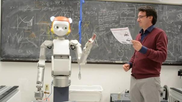
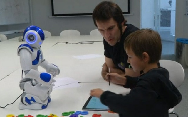
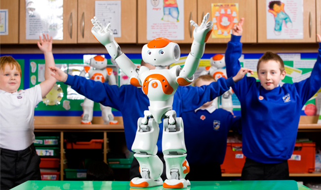
Robotics At The Service Of Autistic Children

With PIRoS (Perception, interaction, social robotics), Mohamed Chetouani created the first French integrated research team in social robotics. Surrounded by clinicians and artificial intelligence experts, he has successfully brought information and communication technologies to the service of children with autism spectrum disorders.

Holder of a thesis in signal processing, Mohamed Chetouani has always relied on interdisciplinarity. This specialist in social robotics integrates the ISIR1 with the desire to put the analysis of human behavior at the heart of its research. He then became interested in autism spectrum disorders (ASD).

” I contacted the head of the child and adolescent psychiatry service at La Pitié-Salpêtrière, David Cohen, to suggest that he use signal processing as part of the analysis of social behavior, recalls Mohamed Chetouani. We have started to conduct studies around ASD. ”

One of the main difficulties with ASD concerns about social interactions and limited and stereotypical interests. To this is often added other deficits such as those related to language, attention or understanding and expression of emotions.

” If psychiatrists have long analyzed children’s behaviors to identify early signs of ASD, it remains difficult and tedious to measure gestures, postures, tone of voice, facial expressions, imitation, etc., parents and children during their interactions, “

Mohamed Chetouani.

However, it is by measuring these interactions more precisely that researchers will be able to improve the still too late diagnosis of this disorder evaluated on average at the age of 3 years.

Analyze behavior through social signal processing

In order to better assess these disorders, the researchers in the PIRoS 2 team help clinicians by automatically analyzing the behaviors involved in social interactions.

“ When two individuals communicate, they signify their attention by looks, smiles, gestures, sounds, etc. This is what we call synchrony. By modeling the behavior of one or more individuals, we can analyze this phenomenon, ”explains Mohamed Chetouani.

By using family films, the researchers thus showed how the synchrony of parent-child interactions made it possible to distinguish early babies with autism from babies without the autistic disorder.

” We then wanted to create our own experimental situations,” specifies the researcher, by opening rooms at Pitié-Salpêtrière with rooms equipped with cameras and microphones to finely analyze social interactions in controlled environments. ”

In this experimental space, Mohamed Chetouani has set up, with his colleagues, research projects bringing together students in engineering sciences and students in psychiatry, speech therapy or psychology. Thanks to this interdisciplinary work, the researchers were able to enrich their studies by comparing conventional clinical measures of social interactions with objective measures resulting from signal processing.

When two individuals communicate, they signify their attention by looks, smiles, gestures, sounds, etc. This is what we call synchrony. By modeling the behavior of one or more individuals, we can analyze this phenomenon.

MOHAMED CHETOUANI

Serious games to improve children’s social interactions

As part of this research, the PIRoS team was also able to test concrete solutions to help children suffering from ASD to develop their social skills. They created serious games intended to train specific skills such as the recognition of emotions, imitation or joint attention. They have thus developed a program on a tablet where the child, after learning to associate an expression, a posture or a gesture with emotion, is invited to reproduce it. Thanks to an emotional recognition algorithm, the JE Mime software is then able to give the player real-time feedback on the quality of his imitation.

Another game developed by the team, the GOLIAH software makes it possible to work on imitation and joint attention using two connected tablets (one for the child, the other for the parents or the therapist). In this game, the child, to evolve, needs to communicate with a third party. The software is also able to measure the child’s interactions. The data collected by the software can be consulted remotely by the therapist and then allow the doctor to better adapt the therapeutic work to be done during sessions at the hospital, school or at home.

” The idea is not that it becomes good on the game of the tablet, but overall improves its social interactions, “

Mohamed Chetouani.

When children teach robots

But the involvement of researchers from the PIRoS team does not stop at the development of serious games. At the Pitié-Salpêtrière hospital, researchers benefit from the existence of a school adapted to children with developmental disabilities. For scientists, it is a real experimental place in which they can study the integration of a robot within a class.

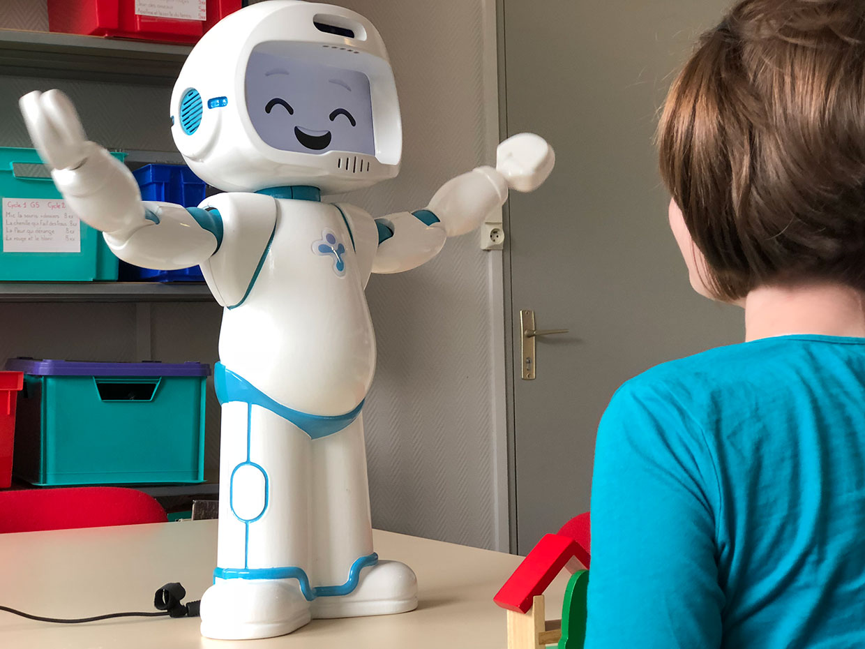
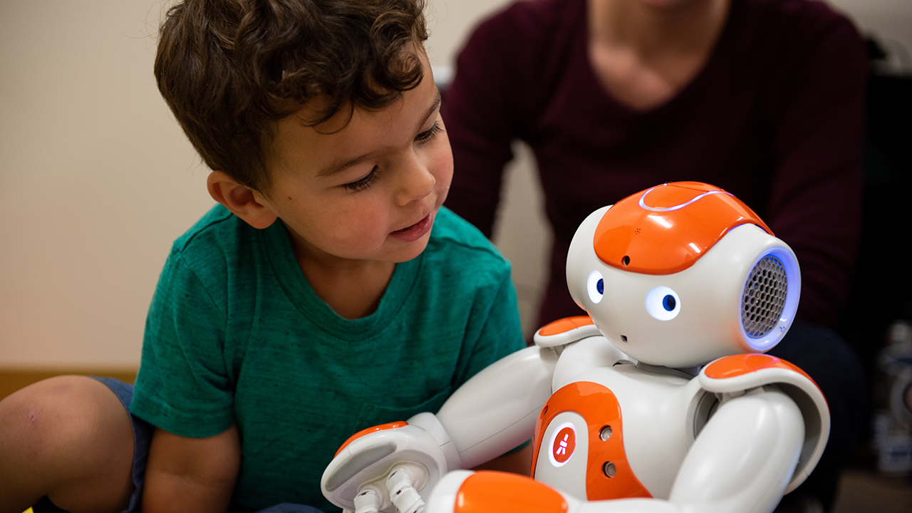
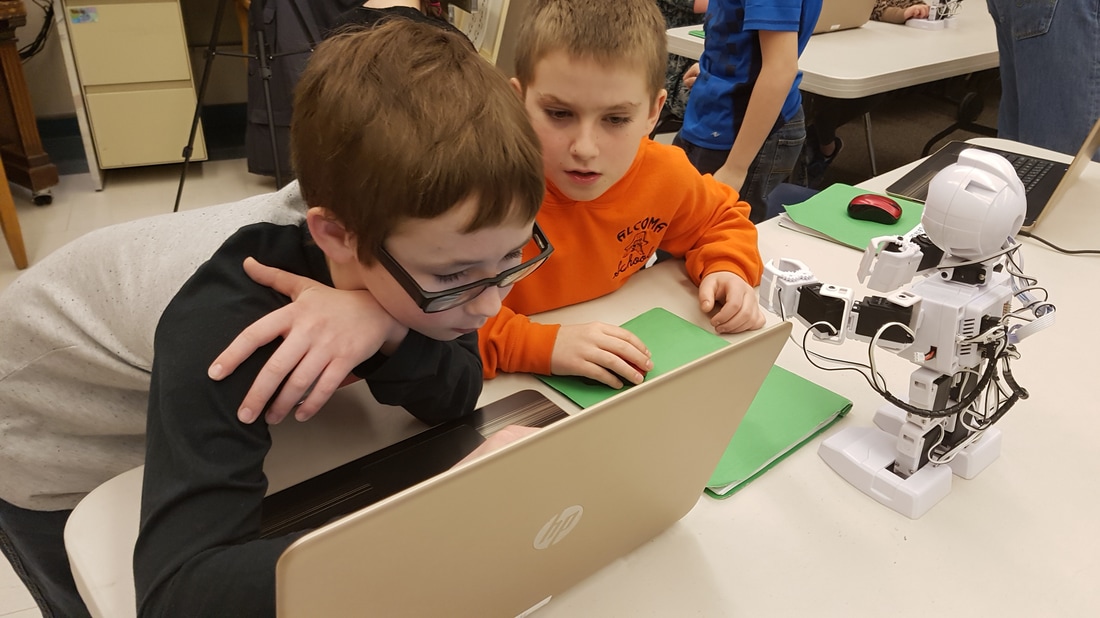
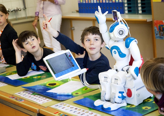
“In robotics, people usually think that robots will help humans. We chose the opposite situation: that of asking the children to teach Nao, a small humanoid robot, ”explains the researcher.

Often passive in conventional therapies, children suffering from ASD are responsible for teaching the robot here. Obliged to communicate and mobilize their skills, they also immediately see the effect of their teaching: if they do the gestures wrong, the robot will perform them badly.

“Teaching the robot greatly values ​​the child who feels responsible for learning Nao,” says Mohamed Chetouani.

The PIRoS team also created a fun and engaging device to stimulate children by asking them to imitate the postures and gestures of the robot. After a few minutes, the roles are reversed and the robot can, in turn, imitate, thanks to artificial intelligence, the movements made by the child.

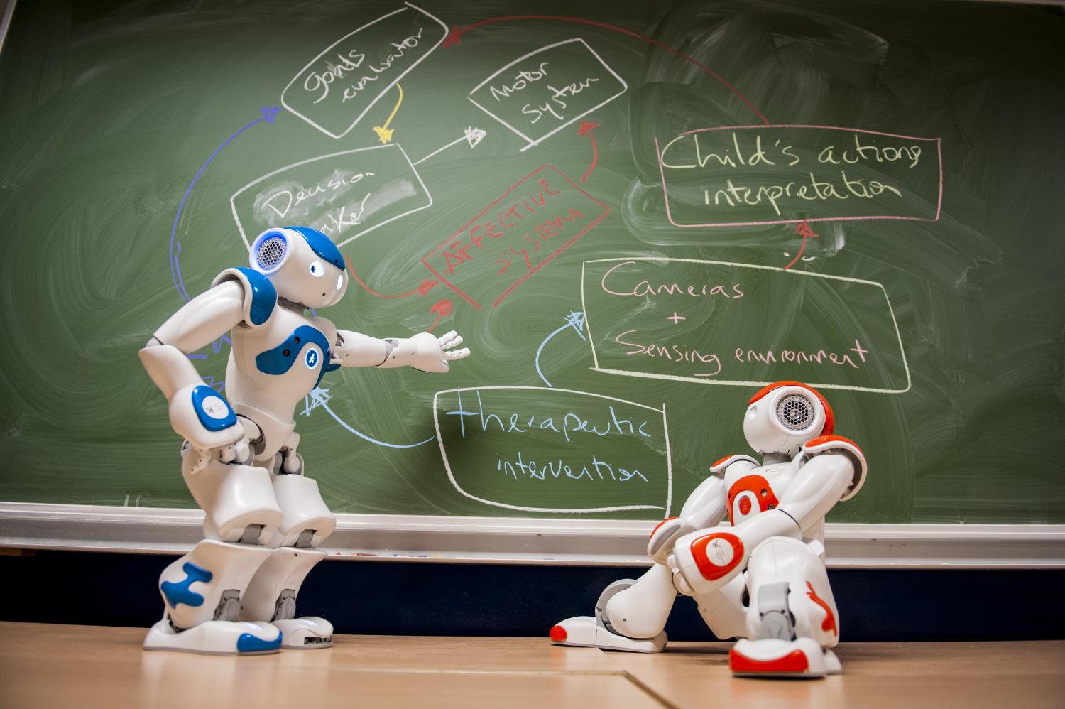
“Thanks to the robot’s sensors, we can follow up with the therapists on the child’s progress thanks to clinical observations but also to objective measures taken by the robot,” says the researcher.

Building on these experiences, Mohamed Chetouani joined the committee of the fourth autism plan in 2018. Its measurement, aimed at evaluating with scientific methods and in everyday situations the technological devices facilitating the learning and the autonomy of autistic people, was chosen. Since then, he has co-led a group of experts responsible for supporting the creation of dedicated experimental centers. These structures which bring together people suffering from ASD and their relatives, but also researchers, clinicians, teachers and entrepreneurs, aiming to develop and evaluate technological innovation for people with autism in order to facilitate their educational and social inclusion.

Teaching the robot greatly values ​​the child who feels responsible for learning Nao.

MOHAMED CHETOUANI

The Use Of Robotics At School

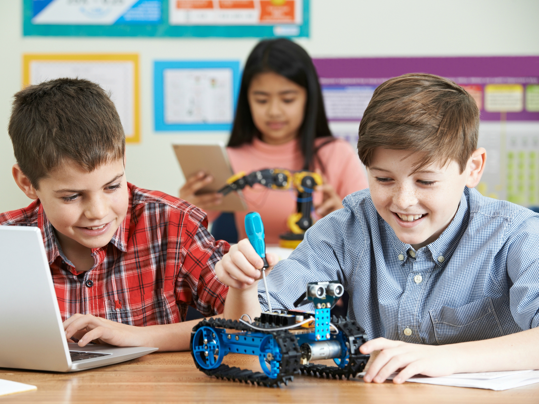
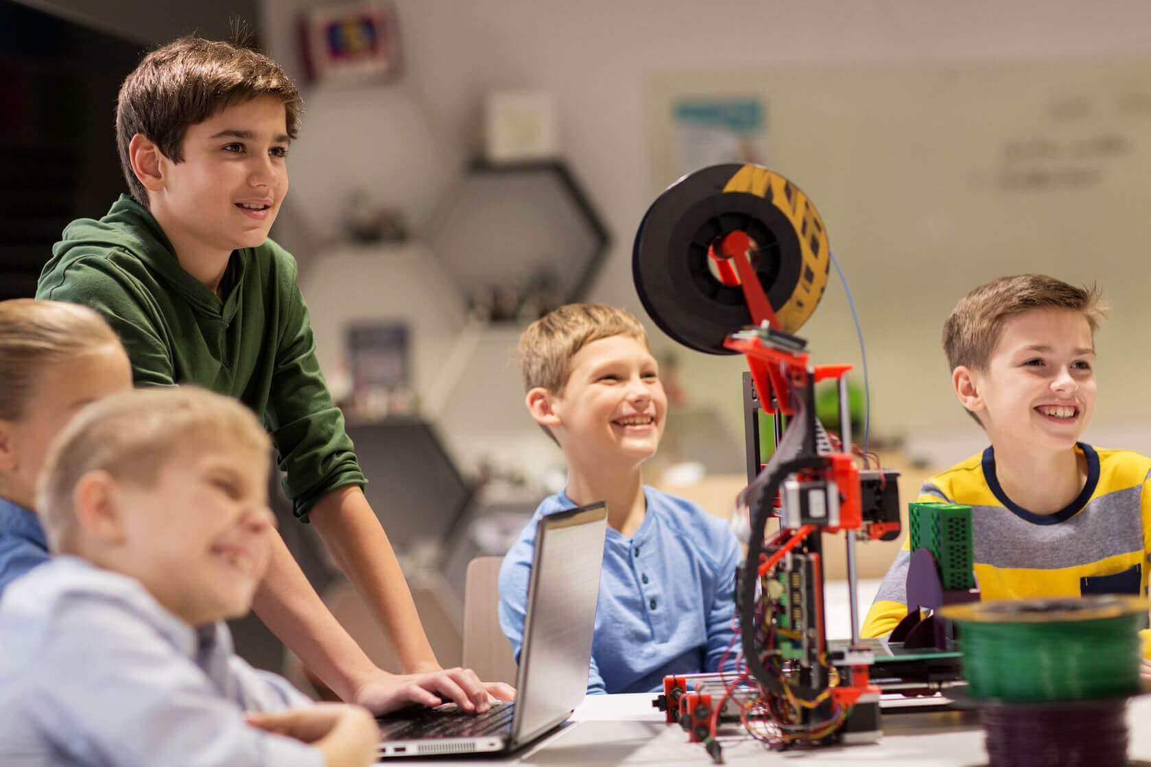
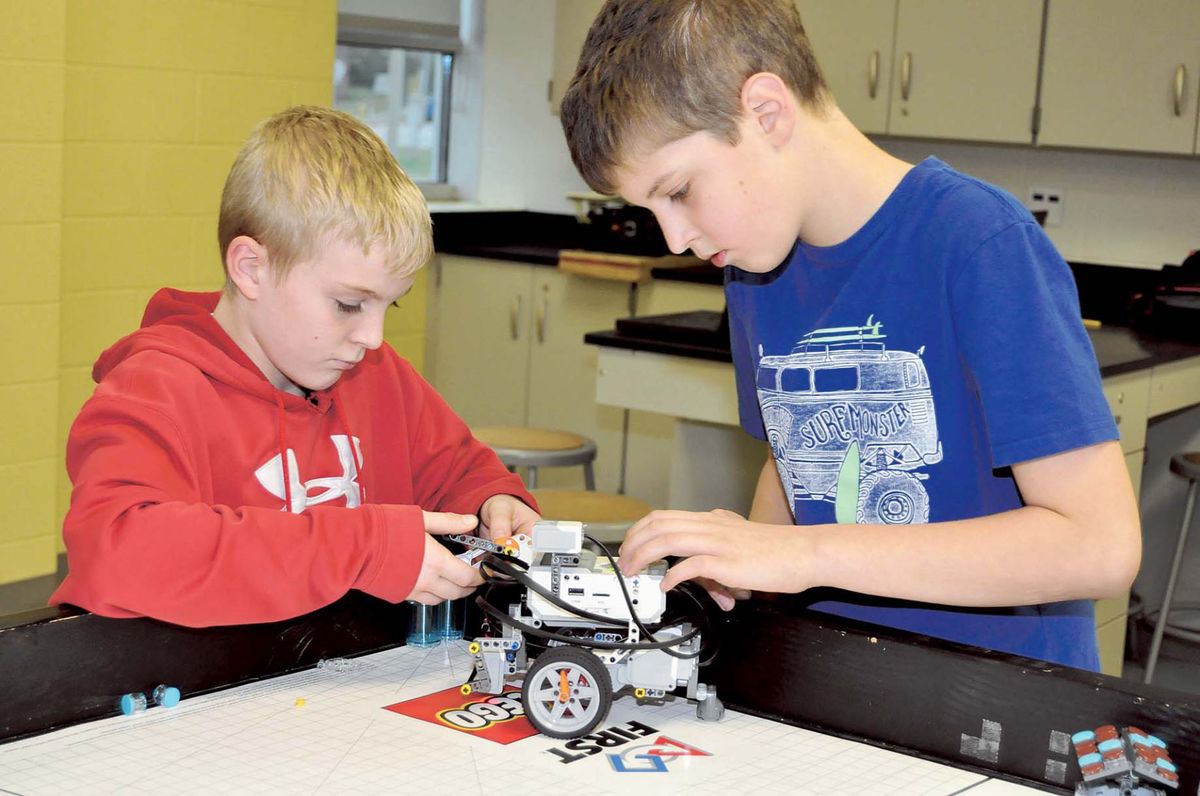
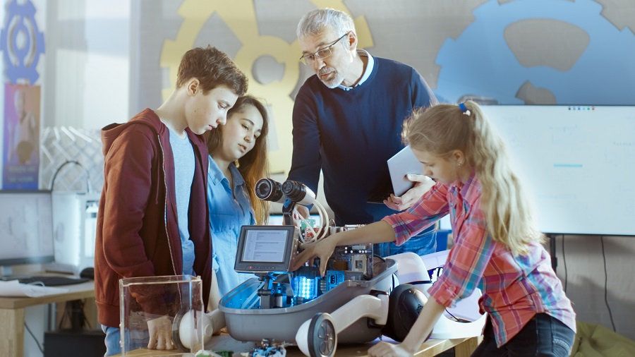
In the educational context, there are three practical educational applications of robotics: the learning of robotics, learning with robotics and learning by robotics. The educational purpose of the latter is the acquisition of mathematical, scientific and technological knowledge and skills, but also the acquisition of transversal skills and the development of students’ cognitive, metacognitive and social skills. The educational interest of this robotic technology is illustrated here by an example of collaboration between teachers and researchers recently carried out in France in a primary school.

Recommendations:

  • Provide a space large enough for students to spread out the material and form groups of maximum 3-4 students per kit
  • Plan short lessons, including problems of increasing complexity in terms of construction and programming, encourage students to find several solutions.
  • Negotiate with students a theme that interests them, enhance the work of students (exhibitions, meetings …)
  • Use tutorials and debriefings throughout problem-solving activities to help students relate the experience to the concepts they acquire.

Robotics For Education

Interest in robotics has greatly increased in recent years. In particular, what arouses interest in constructable and programmable robotic kits for educational contexts is their dimension of “tool with which to think” (Resnick, et al ., 1996). This tool can adapt to different educational objectives and encourage several types of learning.

In fact, from its birth, robotics in an educational environment was designed in this way, and not only as a technology to be mastered . In France, the “digital plan for schools”, aiming among other things to introduce students to computer coding from the start of the 2015 school year, puts a lot into the potential offered by this technology to address notions of computer science, facilitate development skills (for example problem solving), modernize education and help fight against school failure.

The integration and acceptance of any innovative educational technology in teaching are crucial issues, especially since the educational practices supported by the technology are implemented by teachers.

Research must therefore provide answers to their questions such as: Besides computer science and robotics, what subjects can I teach thanks to robotics? What kind of knowledge and skills do students learn when working on robotic projects? What is the role of the teacher in the implementation of these projects? And finally, does it have a real impact on students’ academic results?

Robotic Technology And Educational Purposes


Experimental studies that have looked at the use of robots in an educational context basically show three concrete educational applications (Gaudiello & Zibetti, 2014).

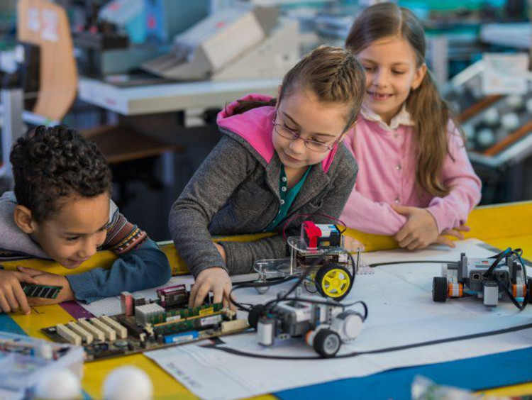
First, learning robotics involves using the robot as a support to learn robotics (i.e. mechanics, electronics and computer science) through practical collaborative activities. The educational aim is therefore the acquisition of knowledge and skills inherent in the construction and programming of robots.

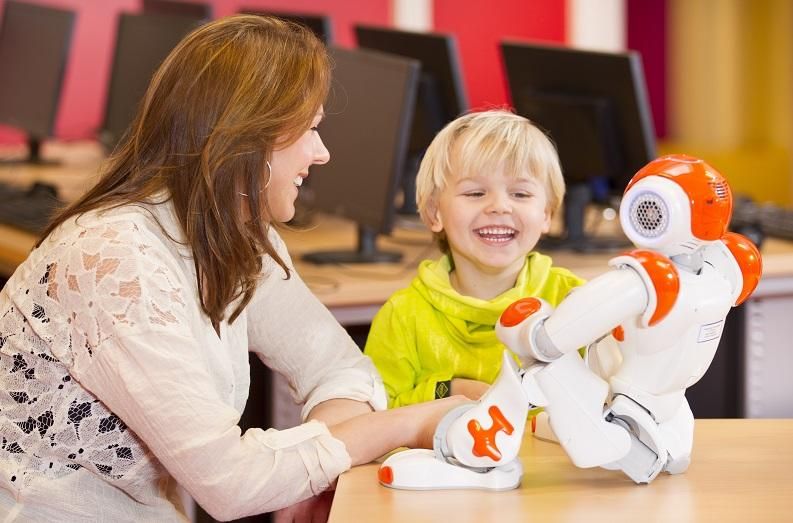
Then, Learning with robotics is based on the interaction between young learners and a humanoid or animoid robot which covers the role of companion for learners or assistant for the teacher. The educational aim is to provoke empathic reactions and to create cognitive and social interactions.

Finally, learning by robotics involves the use of construction and programming robotic kits. The educational aim is the acquisition of knowledge and skills linked to a specific school subject – mathematics, science, technology. But its educational purpose also lies in the acquisition of transversal skills (solving problems, communicating, taking initiatives, etc.) and in the development of students’ cognitive, metacognitive and social skills through self-correction, planning, critical thinking, collaborative work, self-confidence, etc.

What Are The Learning Favored By Robotics?

As with any technological device, it is difficult to maintain that the use of robotics constitutes in itself a real gain for learning. However, a number of studies have demonstrated significant progress in understanding technology (programming, systems), mathematics (distances, fractions, proportions) and the exact sciences (time, temperature, etc.) ( eg, Robinson, 2005). Some more rare studies also demonstrate a contribution of this technology in the learning of SVT ( eg, Gaudiello, 2015), music and art ( eg, Rusk, Resnick, Berg et al . 2008).

Other studies show that the use of robotics at school also brings a real improvement in the development of transversal skills such as scientific reasoning – observation, formulation of hypotheses, manipulation of variables, etc. . ( eg, Sullivan, 2008); attitude towards learning science and the ability to cope with academic failure and to progress ( eg, McDonald and Howell, 2012). The use of robotics also stimulates the development of cognitive skills (consultation of documents, listening, writing reports) metacognitive (structuring and formalization of thought), affective (students engage in meaningful activities) and social (they learn to manage socio-cognitive conflicts) which can be transferred to other areas.

The results of numerous studies show that robotics can have an impact on the acquisition of specific knowledge and on the development of transversal skills.

However, a recent meta-analysis puts these conclusions into perspective (Benitti, 2012). Two points can be raised:

1) Much of the literature on the use of robotics in education is descriptive or anecdotal, based on reports from teachers. Rigorous or longitudinal experimental studies, and in particular with control groups, are rare.
2) The potential of robotics for learning is directly linked to the implementation of an adapted pedagogical approach and scripting.

How To Implement Robotics Activities At School?

Research on pedagogical approaches compatible with the “learn by robotics” paradigm currently constitutes an active area of ​​study within Educational Robotics (Alimisis, 2013; Gaudiello, 2015): this was the subject of the European Pri-Sci project -Net between 2011 and 2014, combining researchers in Education Sciences and Psychology. In this context, educational activities have been designed and tested using robotic technologies for learning science. The workshops took place in a primary school with 25 students from CM1-CM2 and focused on activities developed using an educational approach called IBL ( Inquiry-Based Learning ), which, applied to Sciences, becomes IBSE ( Inquiry Based Science Education). The objective of these workshops was to test the possible benefits of the robotic and IBSE combination.

The IBSE advocates learning based on research and experimentation which draws its philosophy from the founding principles of constructivist theory.

The latter advocates progressive and active learning, where students build their knowledge by alternating phases of practical activities and abstract thinking that allow them to organize new knowledge in mental patterns essential for awareness of their own learning. . Using this approach, students are confronted with open questions or challenges, the answers, and solutions of which involve the acquisition of empirical, collaborative and transferable knowledge (Bell, 2010). The IBSE approach makes it possible to structure educational activities in stages, starting from the formulation of questions on the part of the students on the subject proposed by the teacher, until the resolution of the problem posed while promoting active participation by the class.

One of the workshops tested, called RObeeZ, consisted of creating a robotic hive, including 5 types of robot bees (queen, nurse, mason, guardian, forager). Throughout the school year, the 25 students of a CM1 class built, programmed and perfected these robot bees by working as a team. At the end of the project, exhibitions and seminars for college students were organized to share this educational experience.

The objective of the study was to assess the combined effects of the IBSE approach and robotics on learning processes and on the evolution of academic results. In particular on the acquisition of knowledge in mathematics and in SVT, the acquisition of transversal skills and the development of cognitive, metacognitive and social faculties. To assess these effects, four types of data were collected: quantitative (comparison of transcripts from the first and last quarter of 2014), qualitative (comparison of personal skills reports from the first and last quarter of 2014 made by teachers), student self-assessment (questionnaire including 19 questions on the cognitive, affective, social and metacognitive dimensions of learning, which students had to answer by assigning a score of 0 to 5) and an interview with teachers,

The results show a statistically significant impact on the academic results in mathematics: the marks of the students in problem-solving, geometry, and measurements are higher at the end of the RObeeZ project. On the other hand, no convincing effect was noted on the results in SVT.

At the end of the project, the teachers were invited by the researchers to provide a qualitative assessment of the impact of the RObeez project on the progression of pupils’ skills such as:

consult documents, express themselves orally and in writing in an appropriate vocabulary, organize the data of a problem with a view to its resolution, communicate, practice an investigative process (observe, question, experiment, etc. .), get involved in a project, show persistence, and self-assess. Two groups of students thus emerged, on the basis of the results noted in the skill reports: the group with low progression, and group with strong progression. The results of this qualitative evaluation show a strong progression in the last term for the pupils who were in great difficulty at first.

The self-assessment of the students involved reveals that the project had a positive impact, especially on the affective (appreciation of the project and desire to commit to the realization of a new project) and social (exchange, organize group work) dimensions. ), but also on the cognitive dimension (correction of naive knowledge about bees and robots, acquisition of new knowledge) and metacognitive (becoming aware of the usefulness of technology to learn the content of a lesson, being able to transfer acquired know-how to other projects).

Finally, interviews with teachers reveal that the educational robotics activities supported by the IBSE approach also have an impact on students’ attitudes. The latter is described by the teachers as curious, eager to express their point of view, attentive to their peers, and constant in their commitment to the project. For their part, the teachers testify that the way of conceiving teaching changes in this type of teaching environment: the active participation of the class and the success of the project gave, in their opinion, an important impulse for the implementation of new projects.

Overall, these results appear to be consistent with those of the theoretical and experimental literature on the benefits of educational robotics in schools, especially when the latter is supported by the IBSE approach ( eg, Eguchi & Uribe, 2012).

Conclusion


In view of the studies available on the subject, the integration of robotics into schools is possible when it is “orchestrated” within an adapted educational approach.

It can then stimulate a real transformation in the way of teaching and learning, based on the co-construction of knowledge, skills, and attitudes of students. The combination of robotic activities and the IBSE approach thus seems to allow an in-depth understanding of concepts in mathematics and favor the change of posture of students and teachers. In this context, the complementarity between the two dimensions of “human-oriented” and “technology-oriented” learning could truly deploy its educational potential and encourage students to experience technology as intentional learners and co-authors of their own knowledge and tools. learning.

Dragonfly From Honeybee Robotics, A Geology Lab In A Drone

Honeybee Robotics has been developing robots for several years, especially for space exploration. In recent months, the company has been working on a flying robot capable of landing on rocks and analyzing them.

Honeybee has developed a range of high-performance planetary technologies, including excavation systems, surface geotechnical drilling, exploration and sampling exercises at a depth of 1 to 2 meters, deep drilling under the surface, sample processing, geotechnical systems or sensors, and instruments.

The Dragonfly robot is one of the latest achievements from Honeybee Robotics, and by itself brings together a good part of the company’s expertise.

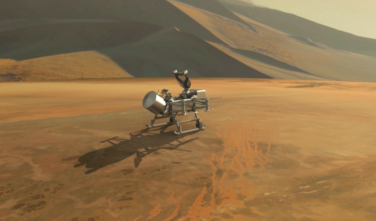
Dragonfly is a rotorcraft that will explore the great moon of Saturn, Titan. The sampling system called Draco ( Drill for Acquisition of Complex Organics )will extract materials from the surface of Titan and deliver them to theDraMS ( Dragonfly Mass Spectrometer, supplied by NASA’s Goddard Space Flight Center ). HoneybeeRobotics will build the end-to-end DrACO system (including hardware, avionics and flight software) and will operate it once the Dragonfly lands on Titan in 2034.


How To Choose The Right LiDAR For Your Project?

Are you looking for a LiDAR with certain specifications but you don’t know which ones are unacceptable to carry out your project? It is sometimes essential to make concessions, it remains to make the right ones.

In this article, we will help you with choosing the right LiDAR for your project. We provide you with some comparisons of the products we sell that are available in the market.

If you have questions about how a LiDAR works or what its parameters mean, take a look at our previous article: What is LiDAR technology?. If you still have questions, don’t hesitate to contact our team.

In this article, we are talking about specifications, which are given by the manufacturers. They may vary depending on your environment.

At first, we chose to highlight the entry-level LiDARs, which have an angular range of 360 °. They are very useful for mobile robots that only require 2D scanning. Only the S1 seems to have good performance for outdoor use. Thanks to these LiDARs, you can obtain information on the proximity of obstacles.

2D LiDARs with an angular range of 360 °

Maker YDLIDAR Slamtec Slamtec Slamtec
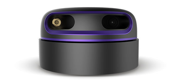
Model YDLIDAR G4 RPLiDAR A2M8 RPLiDAR A3M1 RPLiDAR S1
Price without tax € 266 € 333 € 566 € 569
Type 2D 2D 2D 2D
Wavelength 785nm 785nm 785nm 905nm
Supply voltage 5V 5V 5V 5V
Current consumption 450mA 450mA or less 450mA or less 350mA or less
Consumed strength 2.5W or less 2.5W or less 2.5W or less 1.75W or less
Distance detection (m) 0.2 ~ 16m 0.15 ~ 8m Indoor: 0.15 ~ 10 (black objects) ~ 25m (white objects)
Outdoor use: 0.15 ~ 20m (white objects)
0.2 ~ 10 (black objects)
0.2 ~ 40m (white objects)
Fault distance <2.0m: <0.5mm distance> 2.0m: <1% distance <1.5m: <0.5mm distance> 1.5m: <1% distance <1.5m: <0.5mm distance> 1.5m: <1% ± 5cm
Angular range 360 ° 360 ° 360 ° 360 °
Angular resolution 0.3 ° 0.45 ° ~ 1.35 ° 0.225 ° ~ 0.36 ° 0.313 ° ~ 0.587 °
Not 1090 266 ~ 800 1000 ~ 1600 613 ~ 1150
Scan frequency 5 ~ 12 Hz 5 ~ 15 Hz 5 ~ 20 Hz 8 ~ 15Hz
Temperature range e 0 ~ 50 ° C 0 ~ 45 ° C 0 ~ 45 ° C -10 ~ 50 ° C
Outdoor use NO YES (without direct sunlight) YES (reliable) YES
ROS compatible YES YES YES YES

Below, we compare the high-performance 2D LiDARs. They have an angular range between 190 ° and 270 °. They are useful for precise measurements in order to make decisions safely. They have a scanning frequency of up to 100Hz. The more expensive ones can be used outdoors.

High-performance 2D LiDARs

Maker SICK Hokuyo Hokuyo SICK
Model TIM561-2050101 UST-20LX UTM-30LX LMS511-10100 Pro
Price without tax € 2,131 € 2,280 € 3,985 € 7,652
Type 2D 2D 2D 2D
Wavelength 850nm 905nm 905nm 905nm
Supply voltage 9 ~ 28 VDC 12 / 24VDC 12VDC 24 VDC
Current consumption 450mA or less 150 mA or less 700mA or less 916mA or less
Consumed strength 4W 3.6W or less 8.4W or less 22W
Distance detection (m) 0.05 ~ 10m 0.02 ~ 20m 0.01 ~ 30m 1 ~ 80m
Fault ± 60mm ± 40mm ± 30mm ± 25 mm (1 m… 10 m) ± 35 mm (10 m… 20 m) ± 50 mm (20 m… 30 m)
Angular range 270 ° 270 ° 270 ° 190 °
Angular resolution 0.33 ° 0.25 ° 0.25 ° 0.167 ° / 0.25 ° / 0.333 ° / 0.5 ° / 0.667 ° / 1 °
Not 818 1080 1080 190 ~ 1137
Scan frequency 15 Hz 40 Hz 40 Hz 5 Hz / 35 Hz / 50 Hz / 75 Hz / 100 Hz
Temperature range 0 ~ 50 ° C 0 ~ 45 ° C 0 ~ 45 ° C -10 ~ 50 ° C
Outdoor use NO NO YES YES
ROS compatible YES YES YES YES

The most modern LiDARs are those which can digitize the environment in 3D. You can create an accurate map of the environment to improve the mobility of the robot. The use of 3D space offers new possibilities and functionalities (environment with relief, obstacle clearance, 3D mapping, etc.). These are all long-range scanners that can be used outdoors.

High-performance 3D LiDARs

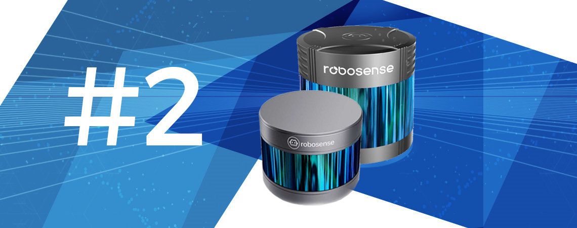
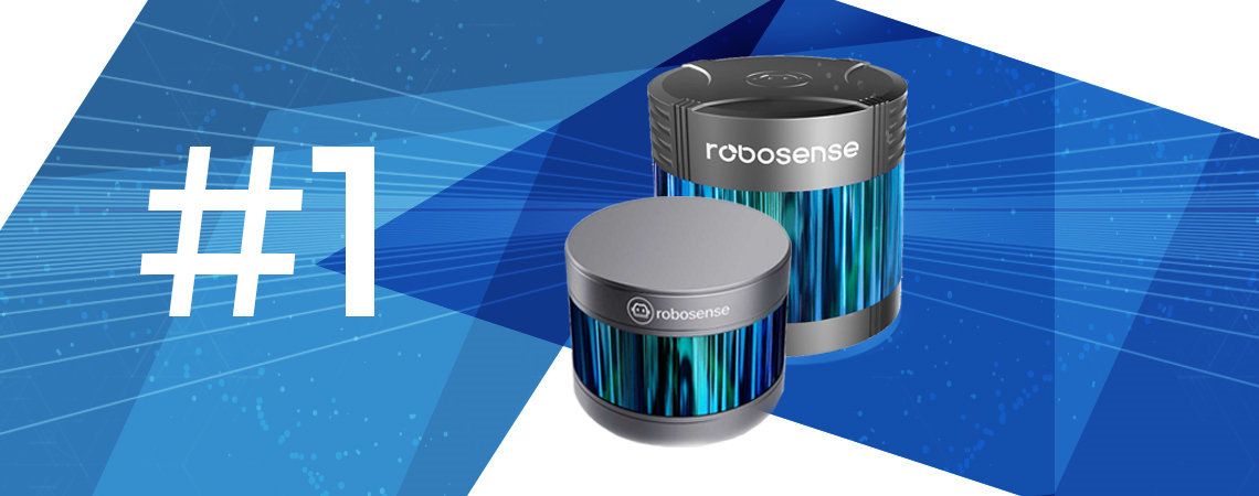
Maker Robosense Velodyne Robosense
Model RS-LIDAR-16 VLP-16 RS-LiDAR-32
Price without tax € 3,440 € 6,000 / 8,000 € 14,990
Type 3D 3D 3D
Wavelength 905nm 903nm 905nm
Number of laser beams 16 16 32
Supply voltage 9 ~ 32 VDC 9 ~ 18 VDC 9 ~ 32 VDCtd>
Consumed strength 9W 8W 13.5W
Distance detection (m) 0.2 ~ 150m 100m 0.2 ~ 150m
Fault +/- 2cm +/- 3cm +/- 3cm
Vertical angular range 30 ° (- 15 ° to + 15 °) 30 ° (-15 ° to + 15 °) 40 ° (- 15 ° to + 25 °)
Horizontal angular range 360 ° 360 ° 360 °
Vertical angular resolution 2 ° 0.4 ° 0.33 °
Horizontal angular resolution 0.09 ° ~ 0.36 ° (5 ~ 20 Hz) 0.1 ° 0.09 ° ~ 0.36 ° (5 ~ 20 Hz)
Vertical steps 15 75 121
Horizontal steps 1000 ~ 4000 3600 1000 ~ 4000
Sampling frequency 75000 ~ 1200000pts / s 1350000 ~ 5400000pts / s 75000 ~ 1200000pts / s
Scan frequency 5 ~ 20 Hz 5 ~ 20 Hz 5 ~ 20 Hz
Rotation speed 300 to 1200 rpm (5-20 Hz) 300 to 1200 rpm (5-20 Hz) 300 to 1200 rpm (5-20 Hz)
Temperature range -30 ~ 60 ° C -10 ~ 60 ° C -30 ~ 60 ° C
Outdoor use YES YES YES
ROS compatible YES YES YES

Finally, we focus on LiDARs intended for outdoor use, they manage to manage the sunlight to obtain an environmental map. They do not all need the same supply voltage and do not consume the same amount of energy.

LiDARs for outdoor use

Maker Slamtec Hokuyo SICK Robosense
Model RPLiDAR S1 UTM-30LX LMS111-10100 RS-LIDAR-16
Price without tax € 569 € 3,985 € 4,289 € 4,128
Type 2D 2D 2D 3D
Wavelength 905nm 905nm 905nm 905nm
Supply voltage 5V 12VDC 10.8 ~ 30 VDC (1 x M12) 9 ~ 32 VDC
Consumed strength 1.75W or less 8.4W or less 8W 9W
Distance detection (m) 0.2 ~ 10m (black objects)
0.2 ~ 40m (white objects)
0.01 ~ 30m 0.5 ~ 20m 0.2 ~ 150m
Fault ± 5cm ± 30mm ± 30mm +/- 2cm
Angular range 360 ° 270 ° 270 ° 360 °
Angular resolution 0.313 ° ~ 0.587 ° 0.25 ° 0.25 ° ~ 0.50 ° 0.09 ° ~ 0.36 ° (5 ~ 20 Hz)
Not 613 ~ 1150 1080 540 ~ 1080 1000 ~ 4000
Scan frequency 18 ~ 15Hz 40 Hz 25 ~ 50 Hz 5 ~ 20 Hz
Rotation speed 2400rpm 1500 ~ 3000 rpm 300 to 1200 rpm (5-20 Hz)
Temperature range -10 ~ 50 ° C -10 ~ 50 ° C -30 ~ 50 ° C -30 ~ 60 ° C
Light intensity limit 10,000Lx or less 40,000Lx or less
Dimensions 60x60x87 mm 102x105x162 mm ø 109 mm x 82.7mm
Outdoor use YES YES YES YES
ROS compatible YES YES YES YES

In this article, we have tried to give you an overview of the different LiDARs available on the market. Indeed, it is necessary to choose your LiDAR according to the intended use of the latter. The different selection criteria can be financial, angular range, scanning frequency, energy consumption, etc.

What Is LiDAR Technology?

Definition – What Is A LiDAR?

A LiDAR is an electronic component that is part of the family of sensors. More specifically, it belongs to the category of time of flight sensors (ToF). A sensor collects data on a physical parameter such as temperature, humidity, light, weight, distance, etc.

The acronym LiDAR stands for Light Detection And Ranging. It is a calculation method that determines the distance between the sensor and the target obstacle. A LiDAR uses a laser beam for detection, analysis, and monitoring.

Physical Phenomenon – How Does It Work?

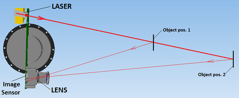
LiDAR technology is a remote sensing technology that measures the distance between the sensor and a target. The light is emitted by the LiDAR and goes towards its target. It is reflected on its surface and returns to its source. As the speed of light is a constant value, LiDAR is able to calculate the distance between it and the target.

By knowing the position and orientation of the sensor, the XYZ coordinate of the reflecting surface can be calculated, represented by a point.

By repeating this process several times, the instrument establishes a complex “map” made up of all the points that LiDAR has collected.

The following diagram explains how a wave refracts on a surface. Part of the wave is reflected at the same angle of incidence (specular reflection), another part is refracted across the surface and the last part is diffusely reflected at different angles of incidence.

Overview Of LiDAR Features

Scanning Technology

This remote sensing technology can be used to measure the distance between the measuring instrument and an obstacle, in this case, we speak of a laser rangefinder. If the sensor scans to obtain the distances between the sensor and the surrounding obstacles, this is called LiDAR.

LiDAR rotates and measures the distance of obstacles over an angular range of up to 360 °, a complete circle. Its speed of rotation depends on the scanning frequency which is between 1 Hz and 100 Hz.

The Different Vision Systems Of LiDAR

There are three types of LiDAR: 1D, 2D or 3D. They work in the same way, the difference lies in the number of dimensions used.

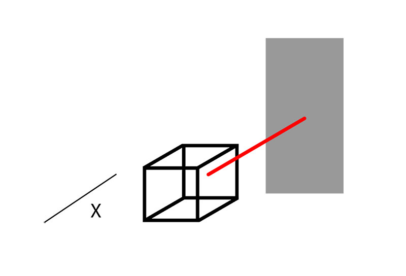
For a 1D laser rangefinder, we need a single fixed laser beam that measures the distance between two points, the data obtained is on an axis and therefore a dimension.

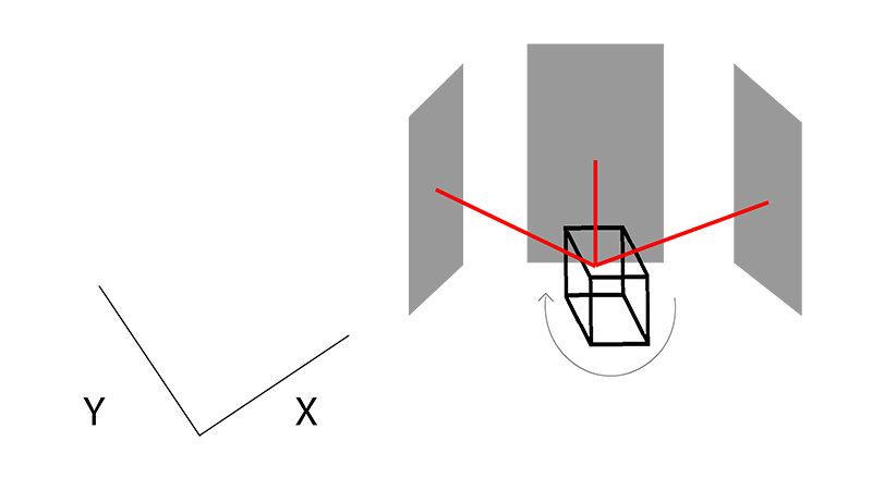
For a 2D LiDAR, only one laser beam is necessary. Indeed, it pulses according to a rotational movement on the horizontal plane and calculates the distance of the obstacles, we obtain data on the X and Y axes.

For a 3D LiDAR, the idea is the same, but there are several laser beams distributed on the vertical axis, always with this horizontal circular scan. We obtain data along three axes X, Y, and Z. Each laser beam will have an angle of difference delta with the other beams on the vertical plane.

Wave Length

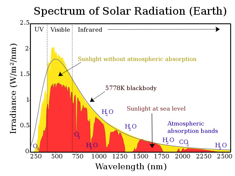
The laser wavelength is an important parameter of LiDAR. Indeed, the sunlight received on the surface of the Earth is distributed over a wide spectrum of wavelengths:

On this graph, some troughs stand out:

  • 750 nm
  • 940 nm
  • 1125 nm
  • 1400 nm

Laser beams more powerful than level 1 can be harmful to the human eye and damage the retina.

LiDARs use the following wavelengths:

  • Infrared (1500-2000 nm) for meteorology / LiDAR Doppler – Scientific applications
  • In the near-infrared (850 -940 nm) for terrestrial mapping
  • Blue-red (500 -750 nm) for bathymetry
  • Ultraviolet (250 nm) for meteorology

Interior Exterior

All LiDARs that comply with these technical standards can be used indoors. Only a few of them can be used outdoors depending on their characteristics. The following factors should be taken into account:

  • Wavelength: at 500 nm, sunlight produces the highest level of disturbance
  • Resistance to ambient light (in Lux): parameter which indicates the amount of light it can accept in order to function properly.
  • The type of surface: transparent surface, smoke, fog, etc.
  • Resistance to ambient noise: rain, snow, terrain, etc.
  • The temperature range: temperature accepted for the proper functioning of the LiDAR
  • Electromagnetic considerations: physical disturbances which can modify the behavior of the sensor

Outdoor LiDARs are more expensive due to their superior performance.

Distance

The range of LiDARs varies between 0.01m to 200m. Depending on the environment, the LiDAR will be exposed to artificial light, sunlight, terrain, transparent elements, etc. Choose a LiDAR with an appropriate distance. Indeed, in indoor use, a detection distance of up to 100m does not necessarily have much interest.

Fault

All LiDARs have two types of errors in their measurement:

Systematic error: this type of error displaces all the measures in a systematic and predictable way. Systematic errors cannot be eliminated, but their influence can be minimized.

Random error: additional errors, due to the environment and physical parameters (refractions, diffraction, etc.), can also occur. A random error occurs when the same exact measurements made by the LiDAR display different values.

The total error over the distance varies from ± 10mm to ± 200mm depending on the LiDARs.

Power Supply

All LiDARs require a power supply. Depending on the expected voltage and the current consumed by the components, the energy consumption or the power consumed can be calculated. When using a battery, this parameter has real importance, in fact, a LiDAR which consumes a lot of energy will shorten the battery cycle of the robot.

Performances

Angular range

This technical specification indicates the possible rotation range of the LiDAR.

For example, a LiDAR with an angular range of 360 ° can perform a full rotation (a full circle) during operation. If this parameter is less than 360 °, the LiDAR will only measure part of its environment, it will have a gray area at each scan cycle.

For a mobile robot, it is important to map all its environment, therefore a LiDAR which has an angular range of 360 ​​° will be a real asset.

Number of positions: step

This parameter indicates the number of positions at which the LiDAR measures during a scan cycle.
For example, a LiDAR with 1024 steps and an angular range of 360 ° will make a measurement for all the Angular range Pas = 360 ° 1024 = 0.35 °.
If the number of steps is too small, the robot will not have enough points to make a safe decision.

Angular resolution

The angular resolution is the result of the previous calculation (0.35 °), it indicates the precision of the LiDAR over its range of rotation. In this example, we will have a point every 0.35 °. Consequently, the smaller this number, the higher the quality of the ‘map’ generated. You should choose this parameter while knowing the necessary precision of the generated environment so that the robot can move there safely.

Scan frequency

This linear parameter indicates the speed of rotation of the LiDAR motor. Indeed, the scanning frequency indicates how many rotations the LiDAR is able to make in 1 second.

  • Scan frequency: 1 Hz
  • Angular velocity: 360 ° / second
  • Rotation speed: 60 rpm (rpm)

For example, a LiDAR which has a scanning frequency of 10 Hz and an angular range of 360 ° will make 10 full rotations per second.

The choice of this parameter is essential when your robot moves quickly in its environment or when the environment moves quickly around the robot. No one likes to make a decision while lacking information.

Scan time

This parameter is: Scan time = 1 Scan frequency = x second / scan.

Points

It is the number of points measured. For a LiDAR with a laser beam, the number of points per scan is equal to the number of steps.

For example, 1024 points/scan means that a LiDAR with a laser beam will have 1024 points or samples in a scan cycle.

Sampling frequency

It is the number of points detected during one second.

For example, a LiDAR with an angular range of 360 °, 1024 steps, and a scanning frequency of 10Hz, the sampling frequency is 1024 * 10 = 10240 points/second.

You can improve one of two parameters (the step or the scanning frequency) to increase the amount of data received in one second.

Communication Interface

The interface, the controller and the communication protocol that will be used with the LiDAR must be able to follow the measurement of the data rate (I2C, PWM, SPI, serial, etc.), so as not to lose any information.
An essential element is to have the same data transmission speed (baud rate) between the LiDAR and the PC or the on-board card. If this speed is too low, the behavior will not correspond to that expected.

ROS

The Robot Operating System (ROS) is a collection of software libraries and tools designed to assist in the creation of robotic applications. From pilots to cutting-edge algorithms and powerful development tools, ROS is now an industry standard for any robotic project. It is an open-source solution.

The LiDARs presented on the Génération Robots site are all ROS compatible. Do not hesitate to consult our selection of LiDARs or to contact us, if you need more information on this technology.

Conclusion – Advantages And Disadvantages Of LiDAR

Benefits Of LiDAR

  • Data can be collected quickly and with great precision
  • LiDAR can easily be integrated with other sensors: sonar, camera, IMU, GPS, ToF sensors
  • LiDAR technology can be used in daylight or in the dark, thanks to an active light sensor
  • Can be used to collect data on places inaccessible to humans
  • LiDARs are fast and very precise. It is a great tool for collecting data over large tracts of land
  • Once properly configured, a LiDAR is a stand-alone technology and can operate on its own.

Disadvantages Of LiDAR

  • LiDAR can be expensive depending on the specifications required by your project
  • LiDARs are ineffective in heavy rain, low clouds, fog or smoke, or in the presence of transparent obstacles
  • Analyzing the huge amount of data collected can take time and resources
  • The powerful laser beams used in some LiDARs can damage the human eye
  • It is difficult to penetrate very dense material

Large Study On The Use Of Robotics In The Classroom – Year 2018

The past few years have seen the rise of the integration of new technologies in classrooms. Robots, allowing young students to grasp programming, to familiarize themselves with new technologies, or to develop scientific thinking, occupy a prominent place in the 2.0 toolbox of many teachers.

Tangible and fascinating objects, they stimulate the attention of students. Robots are real motivational catalysts and through their use, young people develop skills such as collaboration around a project, problem-solving, creativity.

In addition, to be in tune with the new technological society that is being created around us, the French education system has now introduced programming and digital sciences into the school curriculum.

The Génération Robots team has decided to draw up a state of the art on the use of robotics in education, in order to realize the progress made since the beginning in this field.

We, therefore, created a questionnaire that was distributed to various players in the French-speaking educational ecosystem. We then extracted and analyzed the responses we obtained.

To our knowledge, this is the first study of this type. You can view it below, or download it in its entirety here: Use of robotics in the classroom – state of the art in 2018.

Arduino Tutorial – Creation Of A DIY Lamp “LUMINA”

This Arduino based project tutorial was made by an amateur and is mainly intended for other amateurs of the genre or anyone with a little curiosity for this type of electronic assemblies.

The author calls in advance for the benevolence of the venerable experts who would like to dig a little in the code or in the mechanical design (Arduino code and STL files available at the end of the article).

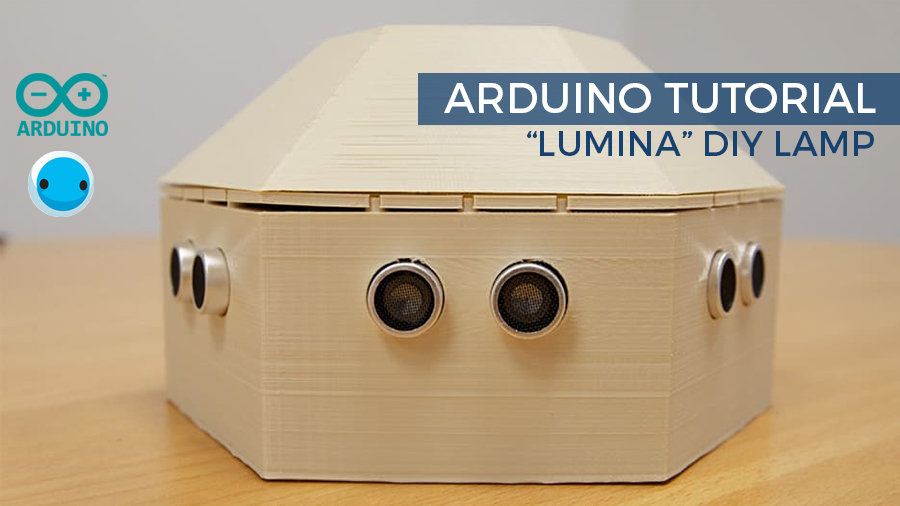
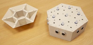
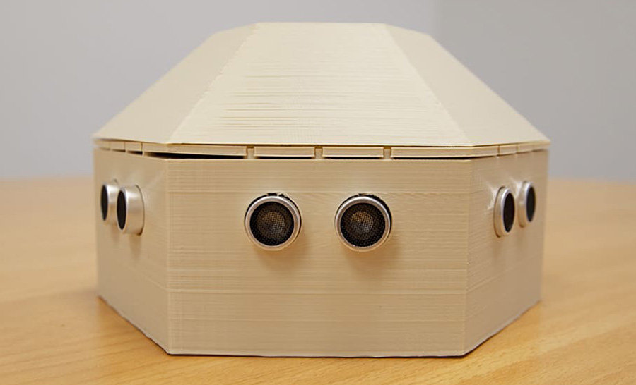
LUMINA is a 3D printed lamp, housing a chain of RGB LEDs whose color and intensity can be varied. It offers several modes, allowing it to be used as a mood lamp or as a game. The interaction is made by means of 6 ultrasonic sensors embedded in the base, which will allow you to navigate between the different modes, and activate the LEDs.

What Equipment Will You Need?

  • 1 x Arduino Uno Rev3 board
  • 1 x USB type B cable
  • 1 x passive piezoelectric buzzer (optional)
  • 1 x 220 Ohm resistor
  • 1 x 400 point prototyping plate
  • Jumper cables M / M and M / F
    (all components available in particular in the Official Arduino Starter Kit )
  • 6 x HC-SR04 ultrasonic sensors
  • 7 x LED grove RGB V2
  • 2 x bags of 5 Grove cables 5 cm
  • Just under 300 g of filament (130g for the box, 65g for the plate and 75g for the cover). In my case, ivory Chromatik filament.
  • The screw 6mm M2 and M2 nuts, or double-sided tape
  • Recommended: 1 x bag of 5 Grove cables / male jumper
  • Optional: 1 x wall charger ( 5V USB adapter or transformer between 7 and 12V for power supply via the jack, for example, this one). Otherwise, plug the USB cable into a computer port.

Software And Libraries To Download

Assembling Your LUMINA Lamp

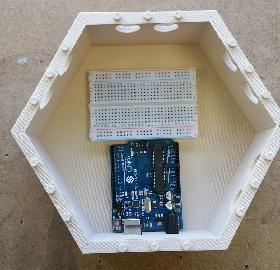
Place the Arduino board in the crate, as close as possible to the interior wall. Then fix the breadboard using the double-sided tape on its underside, so as to prevent the Arduino from moving.

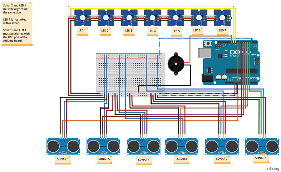
Then proceed to connect the ultrasonic sensors and the buzzer following the Fritzing diagram. When integrating into the body, the sonar 1 must be placed above the Arduino’s USB and jack connectors.

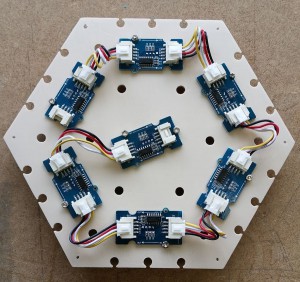
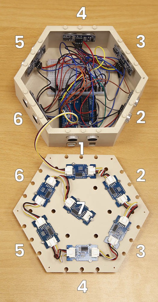
Attach the LED grove modules to the underside of the intermediate plate. If you prefer the use of double-sided tape for screwing, still base yourself on the position of the screw passages, so as to orient the LEDs correctly.

Connect the “IN” of the central LED (number 7) to the “OUT” of one of the peripheral LEDs. Then connect, step by step, the peripheral LEDs. For this, use the 5 cm Grove cables. You can peel the wires from each other, for more flexibility.

The “IN” of the last LED (number 1) must be connected by means of a mixed Grove – male jumper cable, on the one hand to the Arduino (signal), on the other hand to the breadboard (5V and ground ).

Close the box with the intermediate plate, taking care to position the LED 1 (the one which is directly connected to the Arduino) above the sonar 1, ie above the Arduino connectors.

Before closing everything, I recommend that you test the proper functioning of the lamp by uploading the program to the Arduino (the program is available at the bottom of the page, in the resources).

OPTIONAL: screw the plate into the box (for example if you plan to have the lamp handled by children).
Please note, however, that the ultrasonic sensors can be inserted into the body, by simple pressure, which may affect their operation. If you want to screw the plate, provide a way to fix the sensors. Such a system is under consideration with a view to implementation in the very structure of the box.

Position the cover. Normally, all parts should hold in place when fitted. You can then connect the lamp via USB or the jack and start using LUMINA!


Using Your LUMINA Lamp

To date, LUMINA offers 4 modes of use and a selection mode:

Mode 1: Manual Variation

Three ultrasonic sensors will increase the value of the red, green and blue components in stages, and the other three will decrease these same values. The change is applied uniformly to all LEDs. A subroutine makes it possible to modify the value of the level, so as to accelerate the color changes. Accessible by keeping sonars 2 and 5 * activated together.

Mode 2: Automatic Variation

The LEDs scan the spectrum of colors together. It is one of the demo codes of the library used. A subroutine has been added to allow variation of the scanning speed. Accessible by keeping sonars 2 and 5 * activated together.

Mode 3: Light Piano

Each sonar is associated with the LED located above it, itself associated with a color. Activating a sonar light the corresponding LED in its color. When the sonar is no longer activated, the LED gradually decreases in intensity until it goes out.

Several LEDs can be lit at the same time. The top LED lights up white and at its intensity aligned with that of the last activated LED. Each sonar is also associated with a musical note, played by the buzzer as long as the LED is activated. A subroutine allows you to vary the duration of the speed of the gradient from the moment the sonar is released (between approximately 0 and 5 seconds). Accessible by keeping sonars 2 and 5 * activated together.

Mode 4: Simon, The Famous Game

The lamp plays a sequence of LEDs accompanied by notes, which the player must reproduce by activating the corresponding sonars. The game begins with a sequence of 3, incremented with each success, up to a sequence of 10. A success triggers a small animation in green, and advances to the next level. Success at level 10 exits the game. Failure triggers a small red animation and replays the current sequence. The third failure expels the player from the game. The player is subject to a timer to play his sequence. At the end of the timer, the player is eliminated. In all these cases, the lamp returns to Mode 2 – automatic dimming.

This mode is accessible from all modes except Simon, keeping sonars 1 and 4 * activated. LEDs 1 to 4 * light up white and vary in intensity. Activating one of these sonars for a long time will activate the corresponding mode. LEDs 5 and 6 * send the player to automatic variation mode. Ditto when the timer expires.

* number according to photos and Fritzing diagram, not according to code.

Genesis Of The LUMINA Project

I wanted to make this lamp when I saw the videos presenting the Bare Conductive kits (in particular the lamps controlled by a capacitive sensor). I already had a 3D printer, and I noticed that prints that were sufficiently fine could give nice transparency effects, suitable for my use.

I lacked electronics knowledge, but the prospect of being able to make a complete object, thanks to 3D printing, convinced me to get started!

The Choice Of Platforms

The Electronic Card

As I had just started programming in Arduino, I had the famous Uno R3 for beginners. It was only natural to make profitable both the material and the learnings, by basing the project on this card.

That said, it would be possible to use any other card from the Arduino family, or even any other microcontroller ( Raspberry Pi, for those who like to code in Python, for example).

Attention however to those who would like to reproduce the project with a micro: bit: even if it is possible to have access to enough pins thanks to a breakout, the card delivers a voltage of 3.3V, too low to supply the various sensors.

The Sensors

Capacitive sensors in conductive paint would have liked me, but they need to be large enough to be effective. The final object should not be too big, I needed a more compact solution. The ultrasonic sensor HC-SR04 offers the double advantage of being inexpensive and has a wide detection range. For the same use, one could as well have taken infrared sensors, such as those of the manufacturer Pololu.

LEDs

I hesitated for a while with Neopixel RGB LEDs, but the chainable Grove LEDs offer the significant advantage of being very simple to connect, without soldering. Their plate has holes for easy attachment to the structure. On the other hand, the two references have ready-made Arduino libraries.

The 3D Printer

For my part, I use the Neva, from Dagoma. A setting of 0.2 mm (fast) already makes it possible to obtain a very satisfactory rendering. The thin parts do not have any day between the layers, the parts fit together well. I use an ivory-colored filament (the one I use for my tests, in general). Printed quite fine, it allows diffusing the color of the LEDs, while absorbing the excess of brightness.

NB: in its basic dimensions, the box makes the most of the Neva’s printing surface. Be careful to immediately remove the small block that the printer deposits at startup, before the print head returns to it.

Software Tools

The program is carried out in a classic Arduino environment. Small precision, for the ultrasonic sensors, I used the NewPing library. The HC-SR04 are all connected to the same pin for the trigger, and this caused malfunctions with the “basic” Ping library. Note that the MBlock software from the manufacturer MakeBlock allows you to program Arduino boards in a visual language like Scratch.

The modeling of the parts was done with Tinkercad, a free interface accessible online, extremely simple to use. The modeling is done by means of additions and subtractions of more or less complex geometric shapes. However, it allows for very elaborate designs. There are many online video tutorials.

Some Advice

As a beginner, there is something exhilarating about making your first electronic project. On the other hand, it can also be the source of frustration, when faced with unexpected complications or incomprehensible bugs. Here are some suggestions which I hope will help my novice comrades not to become discouraged.

Have A Clear Idea Of ​​What We Want To Do

As in any creative process, one of the main dangers is to get lost along the way, so there are so many possibilities. It will, therefore, be important, throughout the project, to keep the final objective clearly in mind.

Start Small

Rome was not built in a day! If you are a beginner, you must start by agreeing not to do the mega-project-of-the-dead-death-immediately. But don’t worry: your friends are certainly as new as you are, and even a simple assembly based on obstacle detection and LED blinking will be able to make them exclaim with wonder about your new talents as a programmer! And nothing will prevent you from gradually making your editing more complex.

Find A Code Name For Your Project

Because it’s cool. Well, LUMINA may not win the prize for originality, but if you carry out several projects simultaneously, having a small name for each will help you find your way.

Invest In Pencil And Paper

Whenever I wanted to jump straight into a piece of code around an idea, I spent two hours there, where there was really no need to look far. So before jumping on his keyboard, we take a deep breath, sharpen his pencil, sharpen his eraser, and we think. “What is well conceived is clearly stated, and the words to say it come easily.” This maxim by Nicolas Boileau also applies to program! You will see, you will save time!

Go Fishing For Information

It is certain that when working with geeks, it is quite easy to get explanations on obscure points. But for those who are not lucky enough to attend, do not panic! The Internet is full of gold mines, in different forms. First of all, the official websites of the platforms you use will often help you out, be it Arduino, Rasberry Pi, Python, Micro: bit… For basic indications on how Arduino works, the Openclassroom tutorial for beginners is extremely well done. And in general, a simple google with a few well-chosen keywords will get you out of the panic.

Review The Basics

Many programming errors come from a stupid syntax error that we do not see, even though we have read, re-read and re-read its code line by line. A great classic: the notation “if a = 0”, where you should write “if a == 0”. What to go crazy. In case of a bug, very important, therefore, to check even the most basic functions and notations.

Comply With Programming Conventions

Because you may not be the only one reading your code, or simply because you will sometimes need to come back to it after several weeks: follow the good practices in terms of presentation (indentation my love) and comment! Again you will save time and comfort.

Enjoy!

If you are interested in this tutorial, it is probably an amateur programmer. Learning the code is exciting, but can also have its forbidding and restrictive aspects. So as not to get discouraged, always make sure you do something you enjoy!

The Criteria To Look At Before Buying A Robotic Arm

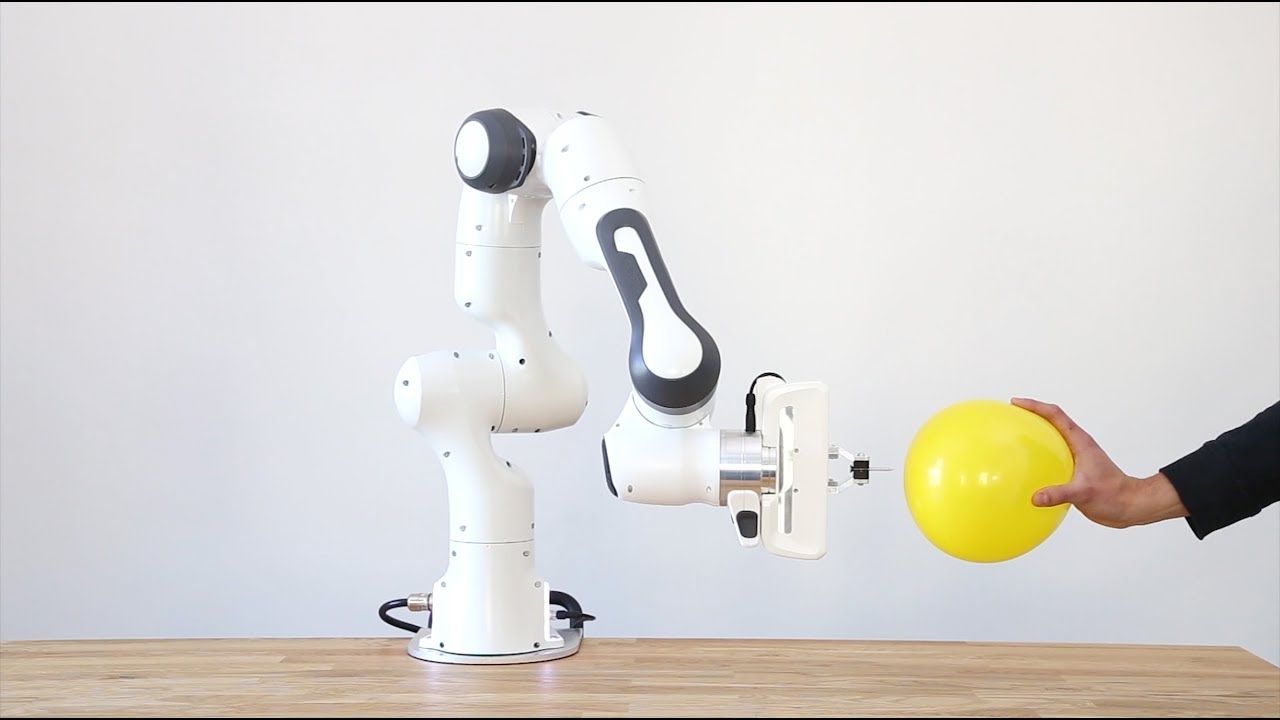
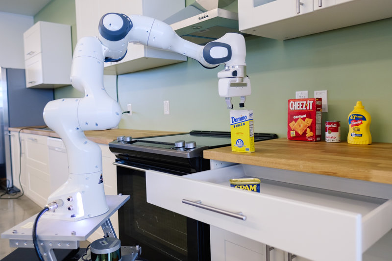
The robotic arms that we distribute are intended for research laboratories, universities, development research units. Here we present a comparison between four large robotic arms, with 6 or 7 axes and ROS compatible.

What Applications For Robotic Arms In Research?

In the laboratory or in the R&D department, robotic arms are used in different fields of study:

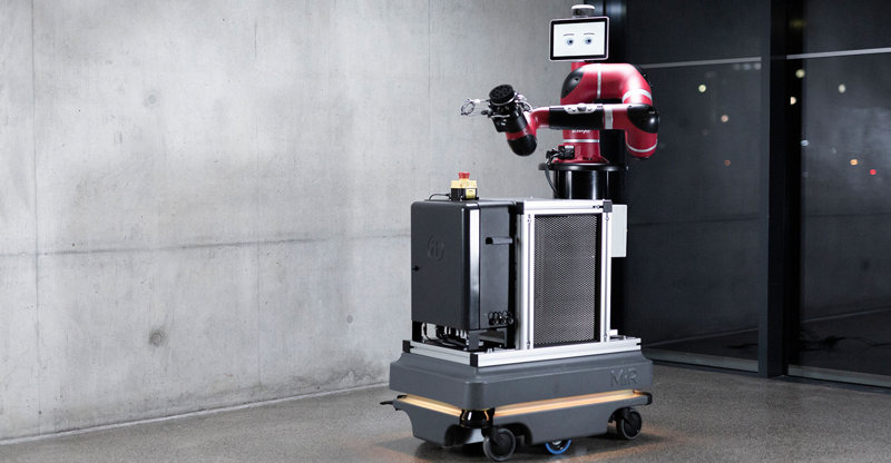
  • Exploration (terrestrial or space), analysis or surveillance, by adjusting a robotic arm on a mobile base
  • E-health, within particular research on smart prostheses (arms controlled by thought)
  • Assistance to the elderly or disabled person, with the programming of robotic arms to perform daily tasks (brewing coffee, folding clothes, etc.)
  • Solidity tests of different products (smartphone screens, smart textiles), etc.

Robotic Arms With 6 Or 7 Degrees Of Freedom

One of the first criteria to take into account when buying a robotic arm is the number of degrees of freedom. The degree of freedom is the ability of a system to move along an axis of translation or rotation.

A robotic arm with 6 axes can reach any point in space, with any given orientation. This makes this type of robot optimal for many tasks.

For example:

  • Grab a tool from the bottom, turn it over and replace it
  • Open a drawer, grab an object and close the drawer
  • Write on a desk or even a wall

A robotic arm with 7 degrees of freedom (DoF) is the closest to the human arm. More agile and faster than a 6DoF arm, it can reach landlocked or enclosed areas, not always accessible by a robot with 6 degrees of freedom.

Strength And Extension

The force ( maximum load ) and the extension of the arm ( maximum range ) are the two other criteria to be taken into account next. In the project you are working on, will the robotic arm lead to carry heavy objects or apply a force to any mechanism? Please note, the higher the loading capacity of a robotic arm, the more it will lose precision.

The extension is the radius of action of the arm, the distance between the base of the arm and its end when the latter is stretched.

Speed ​​And Accuracy

These parameters will be very important if the robotic arm must be brought to interact with small objects for example (or if of course, there is a speed constraint in the application on which you are working).

Thus, the repeatability of the robot (average error when the arm returns to the same point several times), will take on its importance in pick and place applications in a laboratory. If the robot needs to be part of an experiment on home assistance, the high maximum speed will probably not be included in the list of decisive criteria for purchase.

Other Decision Criteria In The Purchase Of A Robotic Arm

We have added five other factors to our checklist:

  • Number of grippers available on the market
  • Compatibility of the robotic arm with ROS
  • A collaborative robot or not (human-robot interaction and nearby work possible in complete safety)
  • Protection index (against humidity, dust, blows)
  • CE marking (compliance of the robot with EU legislation)
  • Budget

IMU And Robotics: What You Need To Know

In this article, we share a lot of information necessary for the purchase of your IMU according to your specifications.
You will find out how an IMU works and how to interpret its parameters.

At the end of the article, you will also find links to tests and resources.

Definition – What Is An IMU?

An inertial measurement unit (IMU) is an electronic component included in the family of sensors. It measures the acceleration of the sensor, the angular velocity and its orientation using a combination of accelerometers, gyroscopes, and magnetometers.

The Type I IMU is made up of accelerometers and gyroscopes, while the Type II IMU includes additional magnetometers.

Accelerometers, gyroscopes, and magnetometers measure data relating to a single axis (X: pitch, Y: roll, Z: yaw). In order to obtain information for the 3 axes, you must integrate three components of each (accelerometers, gyroscopes, and magnetometers) for a Type II IMU. A typical IMU sensor is 9 DoF (degree of freedom) including:

  • 3 accelerometers
  • 3 gyroscopes
  • 3 magnetometers

Some IMUs may have additional degrees of freedom with a temperature sensor, a GPS sensor, a pressure sensor, etc.
Based on acceleration, calculations of attitude, speed, and position can be performed.
Thanks to gyroscopes, the angular position can be calculated.

This data, provided by the IMU, is essential in mobile robotics. Indeed, they complement the LiDAR measurements and the odometric measurements.

Physics – How does an IMU work?

To understand how an IMU works, you must first analyze each subcomponent:

Sub-Component 1: The Accelerometer

An accelerometer is an electromechanical device used to measure acceleration forces. These forces can be:

  • Static, like the force of gravity
  • Dynamics like the forces of movement or vibration

Acceleration is the measure of the change in speed or speed divided by time. For example, a bicycle that accelerates from stopping at 30 km / h in five seconds has an acceleration of 6 km / h per second (30 divided by 5).

Sub-Component 2: The Gyroscope

A gyroscope is a device used to measure or maintain orientation and angular speed. It is a rotating wheel, or a disc, in which the axis of rotation is free to take any orientation by itself.

During rotation, the orientation of this axis is not affected by the inclination or rotation of the support, depending on the conservation of the angular momentum.

Sub-Component 3: Magnetometer

A magnetometer is a device that measures magnetism:

  • His direction
  • His strength
  • The relative change of a magnetic field at a given location

A compass is one such device that measures the direction of an ambient magnetic field. In this case, the Earth’s magnetic field.

ROS – IMU Data Transfer

All ROS-compatible IMU sensors publish their data on the topic/imu in the sensor_msgs / Imu.msg message format:

std_msgs / Header header

geometry_msgs / Quaternion orientation
float64 [9] orientation_covariance

geometry_msgs / Vector3 angular_velocity
float64 [9] angular_velocity_covariance

geometry_msgs / Vector3 linear_acceleration
float64 [9] linear_acceleration_covariance

Orientation

3D rotations and orientation can be represented using the form of Euler angles or in the form of a Quaternion.

Euler Angles

The Euler angles are composed of three angular values ​​for the X, Y and Z axes. Each rotation value is applied sequentially, that is to say successively.

Advantage

Euler angles have an intuitive format “readable to the naked eye”.

Limitation

In some configurations, the Euler angles suffer from a loss of freedom.

Indeed, during the successive application of the three rotations, it is possible that the first or the second rotation results in the third axis pointing in the same direction as one of the preceding axes so that the third value of rotation cannot be applied around a single axis.

Quaternions

Quaternions can be used to represent the orientation or rotation of an object.
Its representation consists of four numbers (referenced in the unit as x, y, z & w).

You should keep in mind that these quantities do not represent angles or axes and that you normally never need to access them directly.

Advantage

Quaternion rotations do not suffer from the loss of a DoF.

Limitation

A single quaternion cannot represent a rotation greater than 180 degrees in any direction and is not intuitively understandable.

Angular Velocity

The angular speed is represented by a three-dimensional vector (x, y, and z), the values ​​of the angular speed depending on the axes x, y, and z.

Linear Acceleration

The linear acceleration is represented by a three-dimensional vector (x, y, and z), the values ​​of linear acceleration depending on the axes x, y, and z.

Covariance

With regard to the sensors, the covariance is the coefficient of confidence relative to the accuracy of the sensor.

Covariance can be static based on sensor performance or continuously updated by changing over time based on the estimate of accuracy. It’s the same for IMU, they can have a static or dynamic covariance.

Each parameter has an associated covariance coefficient, hard-coded or processed by the sensor software, indicating how reliable the value can be.

Overview Of IMU Features

Energy Consumption

To determine the energy requirements of your robotic project, you must take into account the mode and duration of the operation of your machine.

These parameters are important if the sensor operates on battery:

  • Supply voltage in volts
  • Operating current in amperes
  • Wattage

Sensor Specifications

The digital resolution describes the overall detection capacity of your sensor and consists of two parts:

1. The distance => amount of movement that the sensors can take into account:

  • In the case of an accelerometer, this is measured in G forces.
  • Gyroscopes are classified according to the angular speed of rotation that they can quantify in degrees/second.
  • Magnetometers measure their capacities in µT, which can vary depending on the axis of the sensor (x, y, z).

2. Sensitivity => absolute number representing the smallest amount of change that can be measured and detected. For sensors, this is directly related to the number of bits reserved for the sensor in question. The more bits, the higher the sensitivity.

Zero gravity offset: the value of the accelerometer when no external force is applied, which is the minimum error detected.

Zero rate offset: the value of the gyroscope in the absence of angular movement, which may depend on the temperature.

Data rates: the number of measurements made during a given period of time. When choosing your IMU, make sure that the supported sensor rates match the needs of your applications.

Noise density: defined in units per square root bandwidth, typically:

  • ug/sqrt (Hz) for accelerometers
  • deg/s sqrt (Hz) for gyroscopes

Bandwidth: the range of frequencies in which an accelerometer or gyroscope operates.

Interfaces: what cable and communication protocol does the IMU and your embedded system use?

Temperature range: minimum and maximum ambient temperature sensors can operate safely to provide accurate measurements.

Output Parameters

Static precision: the precision of the sensor output when the device is relatively stable/stationary.

Dynamic precision: this is the precision of the sensor output when the device is in motion.

Rotation error: the difference between the output vector and the real vector, measured in degrees.

Heading Error: the difference between the output of the yaw axis and its actual value, measured in degrees.
Heading Drift: error accumulated over time.

RAW Accel / Gyro / Mag: the raw output of each sensor before any treatment.

Calibrated Accel / Gyro / Mag: output from each sensor after sensor fusion has been used to process and clean each signal.

Calibration

After examining the parameters of the sensor outputs, there is something else you need to consider: calibration. The calibration options you choose depend on your budget and the needs of your project.

Nominal: nominal calibration uses average values ​​for the sensor to give it an average performance.

Per-device: calibration by the device allows you to calibrate certain factors, such as the gain of the sensor, specific to each component. Depending on your application, you can choose to calibrate according to a single axis or several axes if your project.

Dynamic: If you find that the nominal calibration is acceptable, the output of your sensor can be further improved dynamically in the field. The characteristics of the sensor vary depending on the temperature and can be adjusted as the sensor is used in its final application.

Data Fusion Algorithms

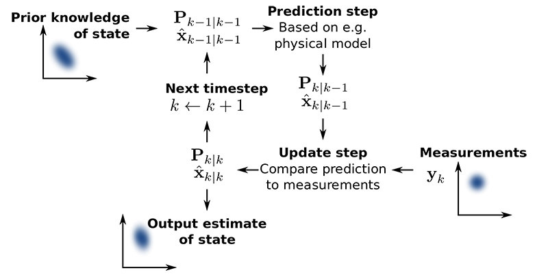
The Kalman Filter

The Kalman filter is a model implementation:

  • First, based on its model, the filter makes an assumption about the next sensor output value
  • He then takes the measured value and compares it with his assumption
  • Finally, he updates his model to make more precise assumptions for the next measurement.

Each sequence of data from the sensors is used to statistically improve the model in order to calculate the outputs. At the same time, the accuracy of the sensors is also judged.

The model depends on the sensor error and the application in question. For mobile robotic systems, real-world knowledge also tells us that physical objects move smoothly and continuously in space, rather than teleporting through space as samples of GPS coordinates might indicate.

This means that if a sensor that has consistently given excellent values ​​consistently starts to tell you unlikely things (like GPS / radio systems when you enter a tunnel), the credit rating of the sensors decreases in a few iterations of a few milliseconds until it begins to measure consistent values ​​again.

It’s better than just averaging because the Kalman filter can support most of its sensors which become temporarily inaccurate. At least one sensor is required which transmits relatively precise values. It ensures the proper functioning of the robot until the other sensors operate again.

The Kalman filter is an application of the more general concepts of Markov chains and Bayesian Inference, which are mathematical systems that iteratively refine their assumptions using evidence.

PID Filters

Simpler robotic systems can be fitted with PID filters. They can be considered as primitive Kalman filters supplied by a single sensor, all the iterative settings being cut and replaced by three fixed values ​​(KP, ki, and kd).

It is a correction system that adjusts the input through the control loop to obtain the correct output.

Even when PID values ​​are set automatically or manually, the whole process of “setting” (adjusting, stealing, judging, repeating) is an outsourced version of Kalman with a human doing the step of spreading beliefs.

Custom Filters

Real systems are often hybrid, somewhere in between.

ROS Packages For IMU

If you implement your robot software under ROS, it will be easier to buy sensors compatible with ROS. This means that the manufacturers have already developed a ROS package to make the sensor interact with ROS. This will save you time.

With regard to the IMU, the sensor will publish the raw or processed data, depending on the implementations of your IMU, on the topic/imu. Then on ROS, you can subscribe to the topic to get data to use it for navigation, for example.

Some ROS packages are already implemented and up to date:

  • imu_transformer: This package provides a node / nodelet combination which can be used to transform IMU data from one TF frame to another
  • imu_tools:
  1. Imu_filter_madgwic: Filter that merges the angular velocities, accelerations and (optionally) magnetic readings of a generic IMU device in an orientation based on the algorithm of Sebastian Madgwick
  2. Imu_complementary_filter: Filter that merges the angular velocities, accelerations and (optionally) magnetic readings of a generic IMU device in a quaternion to represent the orientation of the device on the global frame, based on the algorithm of Roberto G. Valenti
  3. rviz_imu_plugin: a plugin for rviz that displays sensor_msgs:: Imu messages
  • imu_utils: Package that tracks IMU performance on Matlab

How To Choose Your IMU?

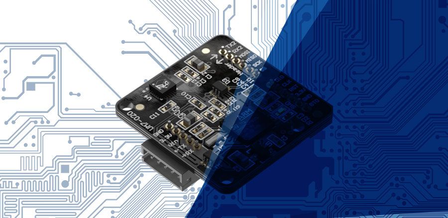
Make your choice according to the requirements of your project. The cheapest IMU provides only raw values, while the UM7 filters the processed values ​​and publishes them directly in a ROS message.

The performance is quite similar even for the most expensive IMUs. The difference is in the additional services and implementations:

  • Integrated calculations
  • Integrated filters (very efficient: IMU SBG Systems )
  • Integrated microcontroller
  • Map library (Arduino, Raspberry pi, etc.)
  • ROS compatibility
  • Interface
  • Integration with GPS data ( Ellipse 2 Micro INS inertial unit from SBG Systems )

What Is The Performance of the IMU?

An IMU sensor is a useful component to add to your robot. It will give you information on attitude, orientation, position, speed, acceleration, rotational speed if the values ​​are calculated.

However, you should keep in mind that the IMU is subject to drift errors. Indeed, errors accumulate over time since the new values ​​are based on the previous ones.

In addition, the IMU, using the magnetic field to calculate values, can be altered by other magnetic fields (motor, metallic structure, etc.) which can give huge errors.

You can implement fixes and filters to reduce this error, but the IMU error will continually drift and increase.

One way to solve this problem is to take into account the value of covariance (confidence coefficient), which can change over time if it is dynamic.

Another way is to add a GPS sensor. Indeed, the GPS signal can update the value of the IMU and correct its drift error.

Looking for real results, you will find online a test of online visualization of the data of an IMU and of an EMG sensor connected to a wrist, which will give you an overview of the error of the IMU (parts 2.1 and 3.1).

This other article lists and describes all the biases of the IMU leading to errors.

Conclusion: Advantages And Disadvantages Of IMU

Benefits Of An IMU

  • The inertial navigation system is independent of all external information and does not consume too much energy
  • The inertial navigation system can provide the location, speed, altitude, angle data, and resulting navigation information is continuous
  • High-frequency measurement and good stability

Limits Of IMU

  • Using information from the integrated navigation system, positioning error increases over time and long-term accuracy is low
  • Long initial alignment time required before each use
  • Time information cannot be given
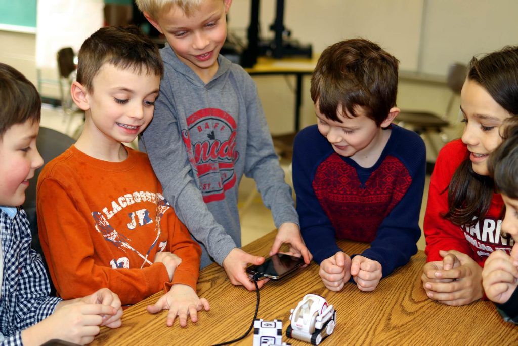
Robots Will Never Replace Teachers But Can Boost Children’s Education

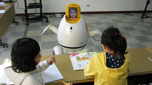
Robots can play an important role in educating young people, but will never completely replace teachers, suggests a new study.

In Science Robotics, scientists explain that social robots are proving effective in teaching certain subjects as restricted as vocabulary or prime numbers.

But the current technical limitations – particularly with regard to speech recognition and the capacity for social interaction – mean that their role will be essentially limited to that of assistants or tutors, at least in the near future.

The study was led by Professor of Robotics Tony Belpaeme, from the University of Plymouth and the University of Ghent, who has worked in the field of social robotics for about two decades.

He said: In recent years, scientists have started building robots for the classroom – not the robot kits used to learn technology and math, but social robots capable of teaching.

The pressures on teaching budgets and the need for more personalized teaching have led to the search for technological solutions.

In the broadest sense, social robots have the potential to be part of the educational infrastructure, just like paper, whiteboards, and tablets.

Robots can free up valuable time for teachers, allowing them to focus on what people still do best: providing a comprehensive, empathetic and rewarding educational experience.

The current study, done in collaboration with academics from Yale University and Tsukuba University, has reviewed more than 100 published articles that have shown that robots are effective in increasing results, mainly due to their physical presence.

However, Professor Tony Belpaeme also explored in detail some of the technical constraints, pointing out that speech recognition, for example, is still not robust enough to allow the robot to understand utterances uttered by young children.

He added that the inclusion of social robots in school curricula would pose significant logistical problems and could actually entail risks, as some children are considered to be too dependent on the help offered by the robots rather than simply using them when they are in trouble.
In their conclusion, the authors add: Besides the practical considerations of introducing robots into education, there are also ethical issues. How far do we want our children’s education to be delegated to machines?

Overall, learners are satisfied with their experiences, but parents and teachers are more cautious.

Despite this, robots hold great promise for teaching small subjects whose results almost match those of human tutoring.

So, although the use of robots in educational environments is limited by technical and logistical challenges at the moment, it is very likely that the classrooms of the future will include robots that will assist a human teacher.